- Claas
- Grove
- New Holland
- Komatsu
- Kubota
- John Deere
- Linde
- Bomag
- CASE
- Clark
- JCB
- Jungheinrich
- Linde
- Yale
- Yanmar
- Manitou
- Manitowoc
- CNH
- Doosan
- Fiatagri
- Fiatallis
- Fiatallis Other Manual PDF
- Flexi Coil
- Ford New Holland
- Ford New Holland Other Manual PDF
- Huyndai
- Hypac
- Hyster
- Hyster Service Manual PDF
- Isuzu
- Kobelco
- Kohler
- Krupp
- Lombardini
- Mahindra
- Nuvera
- Perkins
- Sperry New Holland
- Utilev
- Versatile
- ZF


Komatsu HD465-10, HD605-10 Dump Truck Shop Manual SEN06976-00
$50.00
- Type Of Manual: Shop Manual
- Manual ID: SEN06976-00
- Format: PDF
- Size: 24.5MB
- Number of Pages: 532
Category: Komatsu Shop Manual PDF
-
Model List:
- HD465-10 Dump Truck
- HD605-10 Dump Truck
- 1. Cover
- 1.1. Index and Foreword
- 1.1.1. Index
- 1.1.2. Foreword, Safety, Basic Information
- 1.1.2.1. How to Read the Shop Manual
- 1.1.2.2. Safety Notice for Operation
- 1.1.2.3. Precautions to Prevent Fire
- 1.1.2.4. Procedures If Fire Occurs
- 1.1.2.5. Precautions When You Dispose of Waste Materials
- 1.1.2.6. Engine Technology to Conform Exhaust Gas Emission
- 1.1.2.7. Precautions When You Handle Hydraulic Equipment
- 1.1.2.8. Precautions When You Disconnect and Connect Pipings
- 1.1.2.9. Precautions When You Handle Electrical Equipment
- 1.1.2.10. Precautions When You Handle Fuel System Equipment
- 1.1.2.11. Precautions When You Handle Intake System Equipment
- 1.1.2.12. Practical Use of KOMTRAX
- 1.1.2.13. Disconnect and Connect PushPull Type Coupler
- 1.1.2.14. Precautions for Disconnection and Connection of Connectors
- 1.1.2.15. How to Disconnect and Connect Deutsch Connector
- 1.1.2.16. How to Disconnect and Connect Slide Lock Type Connector
- 1.1.2.17. How to Disconnect and Connect Connector with Lock to Pull
- 1.1.2.18. How to Disconnect and Connect Connector with Lock to Push
- 1.1.2.19. How to Disconnect and Connect Connector with Housing to Rotate
- 1.1.2.20. How to Read the Codes for Electric Cable
- 1.1.2.21. Explanation of Terms for Maintenance Standard
- 1.1.2.22. Standard Tightening Torque Table
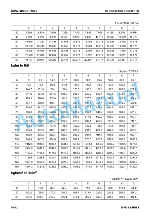
- 1.1.2.23. Conversion Table
- 1.1.2.24. Abbreviation List
- 1.2. Specifications
- 1.2.1. Table of Contents
- 1.2.2. Specifications
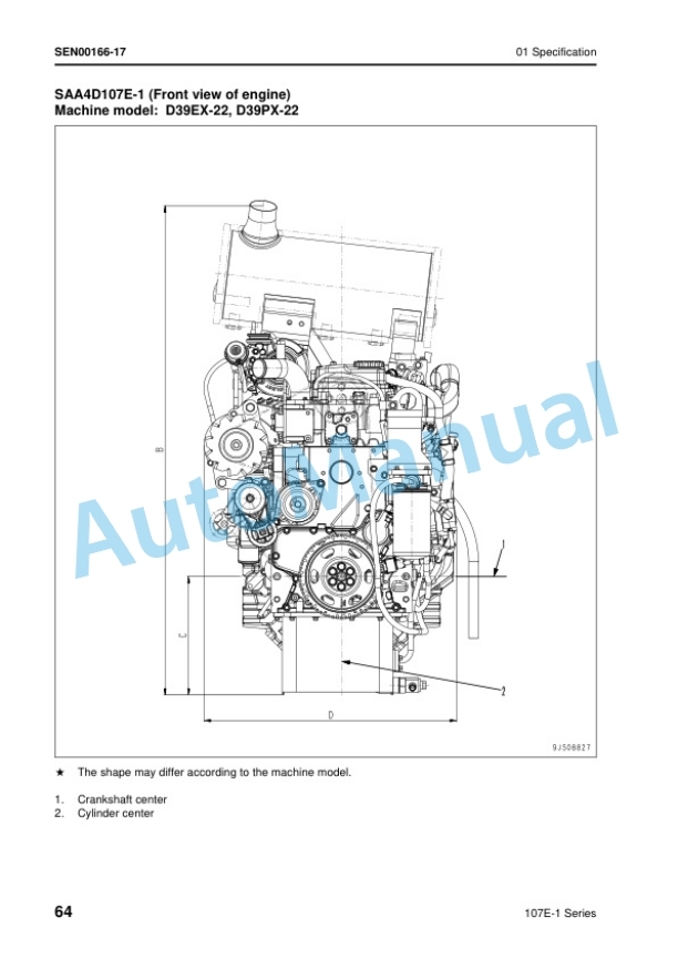
- 1.2.2.1. Specification Drawing
- 1.2.2.2. Specifications
- 1.2.2.3. Weight Table
- 1.2.2.4. Fuel, Coolant, Lubricant
- 1.3. Structure and Function
- 1.3.1. Table of Contents
- 1.3.2. Bootup System
- 1.3.2.1. Layout Drawing of Bootup System
- 1.3.2.2. System Operating Lamp System
- 1.3.2.3. Battery Disconnect Switch
- 1.3.2.4. Engine Shutdown Secondary Switch
- 1.3.3. Engine System
- 1.3.3.1. Layout Drawing of Engine System
- 1.3.3.2. Engine Control System
- 1.3.3.3. Engine Power Mode Selector System
- 1.3.3.4. Automatic Idle Stop System
- 1.3.3.5. Component Parts of Engine System
- 1.3.4. Cooling System
- 1.3.4.1. Layout Drawing of Cooling System
- 1.3.4.2. Radiator Fan Control System
- 1.3.4.3. Component Parts of Cooling System
- 1.3.5. Control System
- 1.3.5.1. Layout Drawing of Control System
- 1.3.5.2. Layout Drawing of Control System (Machine with Mobile Communication Terminal)
- 1.3.5.3. Retarder and Hoist Control System
- 1.3.5.4. Machine Monitor System
- 1.3.5.5. Rearview Monitor System
- 1.3.5.6. KOMTRAX Plus System
- 1.3.5.7. Payload Meter System
- 1.3.5.8. Machine Lockout System
- 1.3.5.9. Component Parts of Control System
- 1.3.6. Hydraulic System
- 1.3.6.1. Layout Drawing of Hydraulic System
- 1.3.6.2. Component Parts of Hydraulic System
- 1.3.7. Power Train System
- 1.3.7.1. Layout Drawing of Power Train System
- 1.3.7.2. Transmission Control System
- 1.3.7.3. Gear Shift Control System
- 1.3.7.4. Direction Control System
- 1.3.7.5. Komatsu Traction Control System (KTCS)
- 1.3.7.6. Travel Speed Limitation System
- 1.3.7.7. Component Parts of Power Train System
- 1.3.8. Work Equipment System
- 1.3.8.1. Work Equipment Control
- 1.3.8.2. Hoist Control
- 1.3.8.3. Component Parts of Work Equipment System
- 1.3.9. Steering System
- 1.3.9.1. Layout Drawing of Steering System
- 1.3.9.2. Secondary Steering System
- 1.3.9.3. Steering Column
- 1.3.9.4. Steering Linkage
- 1.3.9.5. Component Parts of Steering System
- 1.3.10. Brake System
- 1.3.10.1. Layout Drawing of Brake System
- 1.3.10.2. Retarder Control
- 1.3.10.3. ARSC System
- 1.3.10.4. Component Parts of Brake System
- 1.3.11. KOWA Oil Sampling System
- 1.3.11.1. Layout Drawing of KOWA Oil Sampling System
- 1.3.11.2. Function of KOWA Oil Sampling System
- 1.3.12. Undercarriage and Frame
- 1.3.12.1. Suspension
- 1.3.12.2. Front Suspension
- 1.3.12.3. Rear Suspension
- 1.3.12.4. Suspension Cylinder
- 1.3.13. Work Equipment
- 1.3.13.1. Structure of Work Equipment
- 1.3.13.2. Function of Work Equipment
- 1.3.14. CAB Related Parts
- 1.3.14.1. ROPS CAB
- 1.3.14.2. CAB Mount
- 1.4. Maintenance Standard
- 1.4.1. Table of Contents
- 1.4.2. Explanation of Terms for Maintenance Standard
- 1.4.3. Engine and Cooling System
- 1.4.3.1. Maintenance Standard for Engine Mount
- 1.4.3.2. Maintenance Standard for Damper
- 1.4.3.3. Maintenance Standard for Cooling Fan Pump
- 1.4.3.4. Maintenance Standard for Servo Valve for Cooling Fan Pump
- 1.4.3.5. Maintenance Standard for Cooling Fan Motor
- 1.4.4. Power Train
- 1.4.4.1. Maintenance Standard for Drive Shaft
- 1.4.4.2. Maintenance Standard for Torque Converter and Transmission Mount
- 1.4.4.3. Maintenance Standard for Torque Converter and PTO
- 1.4.4.4. Maintenance Standard for Torque Converter Valve
- 1.4.4.5. Maintenance Standard for Transmission
- 1.4.4.6. Maintenance Standard for Transmission Control Valve
- 1.4.4.7. Maintenance Standard for H, L, 4th, 3rd, R, 2nd, and 1st ECMV
- 1.4.4.8. Maintenance Standard for Lockup Clutch ECMV
- 1.4.4.9. Maintenance Standard for Front Axle
- 1.4.4.10. Maintenance Standard for Rear Axle
- 1.4.4.11. Maintenance Standard for Differential
- 1.4.4.12. Maintenance Standard for Final Drive
- 1.4.5. Steering System
- 1.4.5.1. Maintenance Standard for Steering Column
- 1.4.5.2. Maintenance Standard for Steering Linkage
- 1.4.5.3. Maintenance Standard for Demand Valve
- 1.4.5.4. Maintenance Standard for Steering Cylinder
- 1.4.6. Brake System
- 1.4.6.1. Maintenance Standard for Slack Adjuster
- 1.4.6.2. Maintenance Standard for Front Brake
- 1.4.6.3. Maintenance Standard for Rear Brake
- 1.4.7. Undercarriage and Frame
- 1.4.7.1. Maintenance Standard for Front Suspension Cylinder
- 1.4.7.2. Maintenance Standard for Rear Suspension Cylinder
- 1.4.8. Hydraulic System
- 1.4.8.1. Maintenance Standard for Pump Assembly (Steering, Hoist)
- 1.4.8.2. Maintenance Standard for Servo Valve of Pump Assembly (Steering, Hoist)
- 1.4.8.3. Maintenance Standard of Pump Assembly (Power Train and Brake Cooling)
- 1.4.8.4. Maintenance Standard of Pump Assembly (Brake Cooling and Control)
- 1.4.8.5. Maintenance Standard for Hoist Valve
- 1.4.9. Work Equipment
- 1.4.9.1. Maintenance Standard for Hoist Cylinder
- 1.4.10. CAB Related Parts
- 1.4.10.1. Maintenance Standard for CAB Mount
- 1.5. Circuit Diagrams
- 1.5.1. Table of Contents
- 1.5.2. How to Read the Codes for Electric Cable
- 1.5.3. Hydraulic Circuit Diagram
- 1.5.3.1. Symbols Used in Hydraulic Circuit Diagram
- 1.5.3.2. Hydraulic Circuit Diagram (1/3)
- 1.5.3.3. Hydraulic Circuit Diagram (2/3)
- 1.5.3.4. Hydraulic Circuit Diagram (3/3)
- 1.5.3.5. Power Train Hydraulic Circuit Diagram
- 1.5.4. Electrical Circuit Diagram
- 1.5.4.1. Symbols Used in Electric Circuit Diagram
- 1.5.4.2. Electrical Circuit Diagram of Inside of CAB (1/10)
- 1.5.4.3. Electrical Circuit Diagram of Inside of CAB (2/10)
- 1.5.4.4. Electrical Circuit Diagram of Inside of CAB (3/10)
- 1.5.4.5. Electrical Circuit Diagram of Inside of CAB (4/10)
- 1.5.4.6. Electrical Circuit Diagram of Inside of CAB (5/10)
- 1.5.4.7. Electrical Circuit Diagram of Inside of CAB (6/10)
- 1.5.4.8. Electrical Circuit Diagram of Inside of CAB (7/10)
- 1.5.4.9. Electrical Circuit Diagram of Inside of CAB (8/10)
- 1.5.4.10. Electrical Circuit Diagram of Inside of CAB (9/10)
- 1.5.4.11. Electrical Circuit Diagram of Inside of CAB (10/10)
- 1.5.4.12. Electrical Circuit Diagram of Machine (1/7)
- 1.5.4.13. Electrical Circuit Diagram of Machine (2/7)
- 1.5.4.14. Electrical Circuit Diagram of Machine (3/7)
- 1.5.4.15. Electrical Circuit Diagram of Machine (4/7)
- 1.5.4.16. Electrical Circuit Diagram of Machine (5/7)
- 1.5.4.17. Electrical Circuit Diagram of Machine (6/7)
- 1.5.4.18. Electrical Circuit Diagram of Machine (7/7)
- 1.5.4.19. Electrical Circuit Diagram of Engine (1/2)
- 1.5.4.20. Electrical Circuit Diagram of Engine (2/2)
- 1.6. Index
Rate this product
You may also like
Komatsu Shop Manual PDF
$50.00
Komatsu Shop Manual PDF
$50.00


- Claas
- Grove
- New Holland
- Komatsu
- Kubota
- John Deere
- Linde
- Bomag
- CASE
- Clark
- JCB
- Jungheinrich
- Linde
- Yale
- Yanmar
- Manitou
- Manitowoc
- CNH
- Doosan
- Fiatagri
- Fiatallis
- Fiatallis Other Manual PDF
- Flexi Coil
- Ford New Holland
- Ford New Holland Other Manual PDF
- Huyndai
- Hypac
- Hyster
- Hyster Service Manual PDF
- Isuzu
- Kobelco
- Kohler
- Krupp
- Lombardini
- Mahindra
- Nuvera
- Perkins
- Sperry New Holland
- Utilev
- Versatile
- ZF