


Komatsu Service Manual PDF
$40.00
Komatsu Service Manual PDF
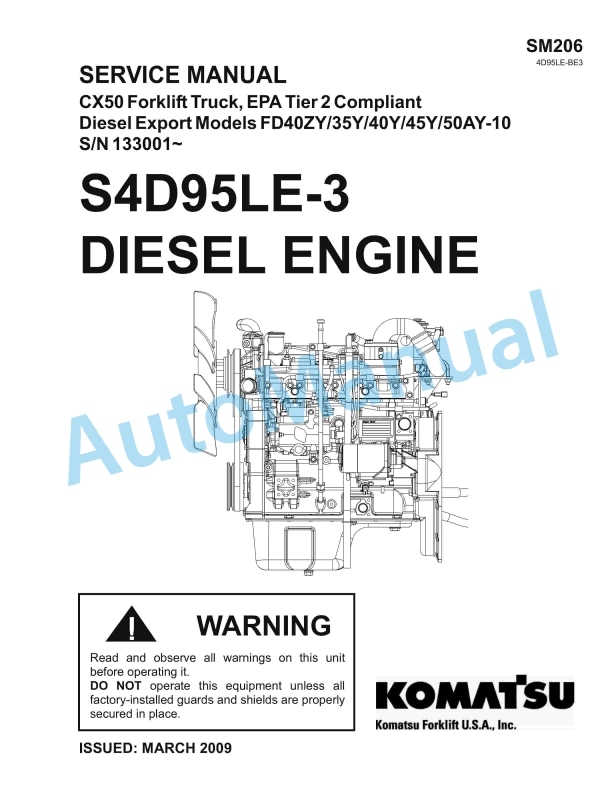
Komatsu CX50 Forklift Truck EPA Tier 2 Compliant Service Manual SM206
$40.00
Komatsu Service Manual PDF
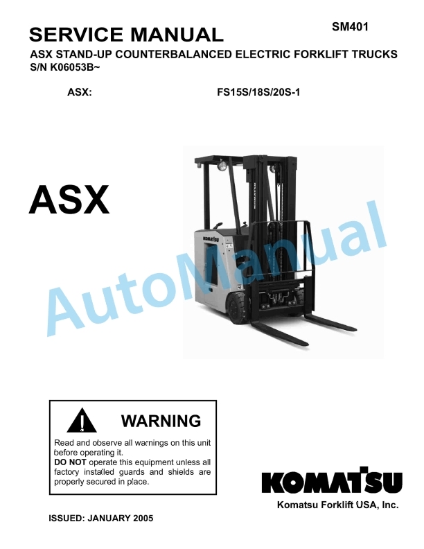
Komatsu ASX Stand-up Counterbalanced Electric Forklift Truck Service Manual SM401
$40.00