


Komatsu Service Manual PDF
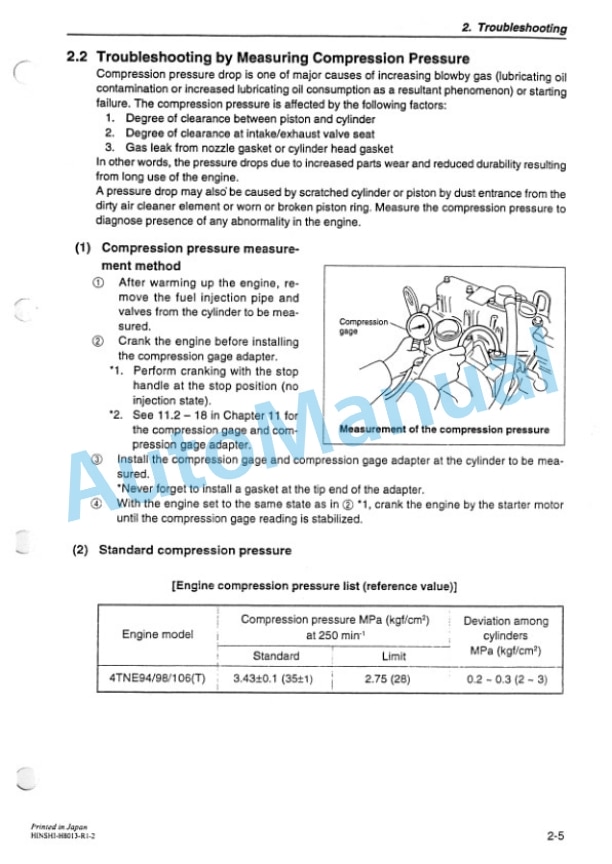
Komatsu 4TNE94.98.106T Diesel Engine Service Manual HINSHI-H8013-R1
$40.00
Komatsu Service Manual PDF
Komatsu G421, G422, G521, G522, G523 Transmission Service Manual 2975 413 M1
$40.00
Komatsu Service Manual PDF
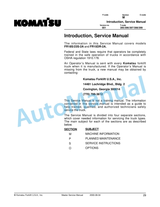
Komatsu FR18S-2A, FR23S-2A, FR15DR-2A Forklift Truck Service Manual
$40.00
Komatsu Service Manual PDF
Komatsu FB10M-2, FB13M-2, FB15M-2, FB18M-2 Forklift Truck Service Manual SM018
$40.00