


Komatsu Service Manual PDF
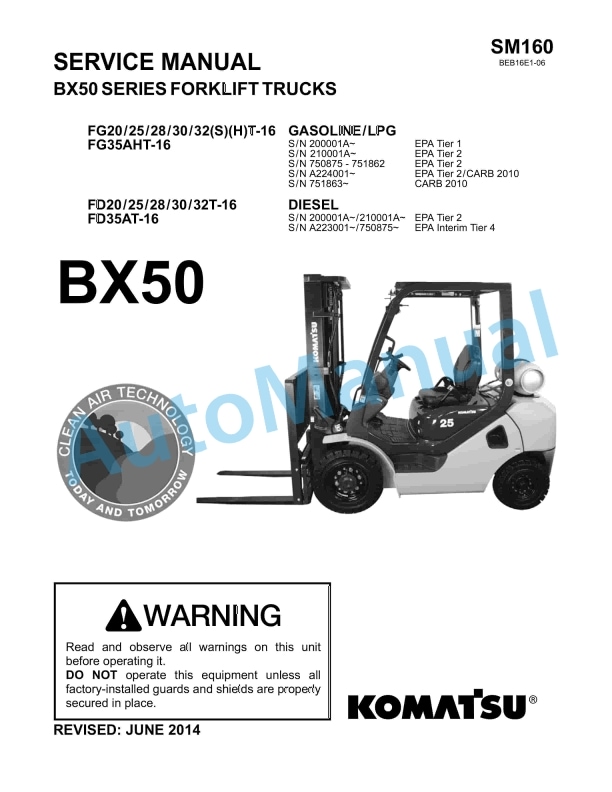
Komatsu CX50 Forklift Truck EPA Tier 2 Compliant Service Manual SM206
$40.00
Komatsu Service Manual PDF
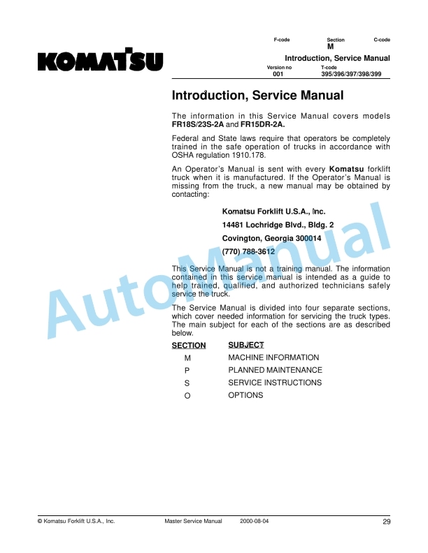
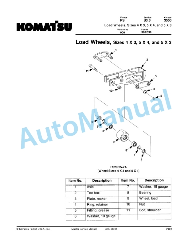
Komatsu FR18S-2A, FR23S-2A, FR15DR-2A Forklift Truck Service Manual
$40.00
Komatsu Service Manual PDF
Komatsu CX50 Forklift Truck EPA Tier 2 Compliant Service Manual SM206
Komatsu Service Manual PDF
Komatsu FR18S-2A, FR23S-2A, FR15DR-2A Forklift Truck Service Manual