No products in the cart.
Return to shop
$50.00
Komatsu Shop Manual PDF
Komatsu 102 Series Diesel Engine Shop Manual SEBM010019
Komatsu 102 Series Diesel Engine Shop Manual SEBM010023
Komatsu 102 Series Diesel Engine Shop Manual 6D102E-BE4
Komatsu 102 Series Diesel Engine Shop Manual YEBM200101
Komatsu 102 Series Diesel Engine Shop Manual SEBM010026
Komatsu 100, 125, TD-7, TD-8 Series C,E Loader Shop Manual ISS-1543
Komatsu 107E-3 Series Engine Shop Manual SEN06655-01
Komatsu 107E-5 Series Engine Shop Manual SEN06896-02
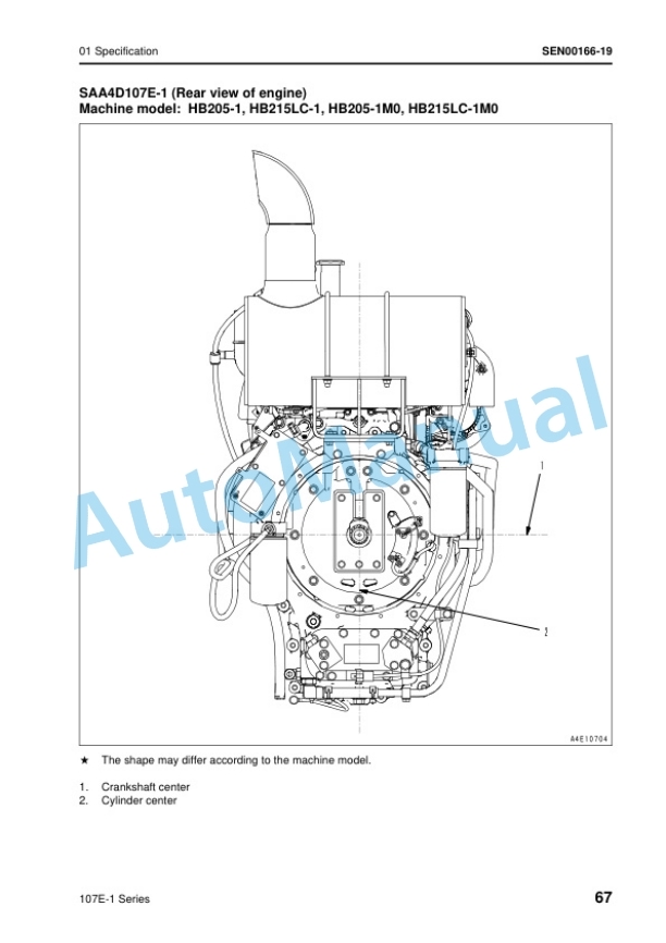
Komatsu 107E-1 Series Engine Shop Manual SEN00161-28
Komatsu 102 Series Diesel Engine Shop Manual SEBM030700


