Komatsu PC3000-1 Hydraulic Mining Shovel Shop Manual SMPC30006194
$40.00
- Type Of Manual: Shop Manual
- Manual ID: SMPC30006194
- Format: PDF
- Size: 16.9MB
- Number of Pages: 460
Category: Komatsu Shop Manual PDF
-
Model List:
- PC3000-1 Hydraulic Mining Shovel
- 1. Main Menu
- 2. Cover
- 3. Introduction
- 4. Foreward
- 5. Table of Contents
- 6. Section 1 Main Assembly Groups
- 6.1. Table of Contents
- 6.1.1. General Layout
- 6.1.2. Drive
- 6.1.3. Control Blocks, Swing Gear
- 6.1.4. Undercarriage, Travel Drive
- 6.1.5. Drivers Cab
- 7. Section 2 Drive
- 7.1. Table of Contents
- 7.1.1. Prime Drive Assembly
- 7.1.2. Engine Mounts
- 7.1.3. Fan Drive and Cooler Assembly
- 7.1.4. Coupling
- 7.1.5. Air Filter
- 7.1.6. Pump Distributor Gear
- 7.1.7. Spline Lubrication
- 7.1.8. Gear Lubrication
- 7.1.9. Location of Pumps, Drive Speeds, and Flow Rates
- 8. Section 3 Hydraulic Oil Tank
- 8.1. Table of Contents
- 8.1.1. Main Oil Tank
- 8.1.2. Return and Leak Oil Filter
- 8.1.3. Breather Filter
- 8.1.4. Location of Pressure Switches and Sensors
- 9. Section 4 Hydraulic Oil Cooling
- 9.1. Table of Contents
- 9.1.1. General
- 9.1.2. Hydraulic Oil Cooling Circuit
- 9.1.3. Measuring / Setting the Back Pressure Valve
- 9.1.4. Fan Drive
- 9.1.5. Pressure Relief Valve and Solenoid Valve
- 9.1.6. Axial Piston Pump
- 9.1.7. Measuring and Setting the Fan Speed
- 9.1.8. Function Check for RPMControl
- 10. Section 5 Controlling
- 10.1. Table of Contents
- 10.1.1. Pilot Pressure Supply
- 10.1.2. Checks and Adjustments of Pilot Pressure
- 10.1.3. Measuring and Adjustment of Control Pressure
- 10.1.4. Travel Parking Brake
- 10.1.5. Function Check of Travel Parking Brake
- 10.1.6. Function Check of Pressure Switch (B48)
- 10.1.7. Swing Parking (House) Brake
- 11. Section 6 Components
- 11.1. Table of Contents
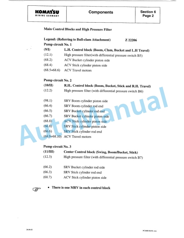
- 11.1.1. Main Control Blocks and High Pressure Filter
- 11.1.2. Distributor Manifold
- 11.1.3. Restrictor Block with Pressure Relief Valve
- 11.1.4. Restrictor Block
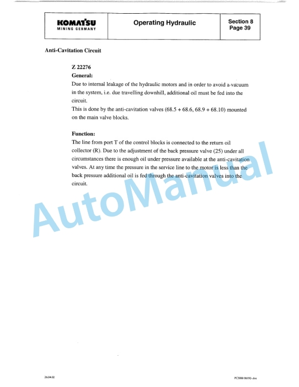
- 11.1.5. AntiCavitation Valve Block
- 11.1.6. Proportional Solenoid Valve
- 11.1.7. Pressure Filter
- 11.1.8. Control Blocks
- 11.1.9. Travel Brake Valve
- 11.1.10. Pressure Reducing Valve
- 11.1.11. Directional Control Valves (Solenoid Valve)
- 11.1.12. Hydraulic Cylinder
- 11.1.13. Auxilliary Pumps (Fan Drive)
- 11.1.14. Auxilliary Gear Pumps
- 11.1.15. Swing Ring
- 12. Section 7 Main Hydraulic Pumps
- 12.1. Table of Contents
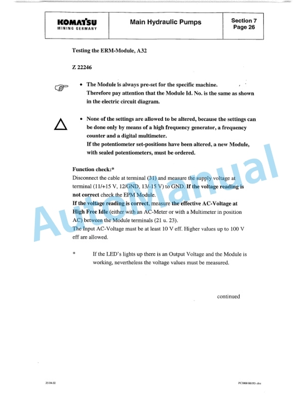
- 12.1.1. Main Hydraulic Pump A7V / HD D
- 12.1.2. SLbearing
- 12.1.3. Function of the Pump Governor
- 12.1.4. Pump Bearing Lubrication
- 12.1.5. Pump Governor Adjustments
- 12.1.6. Pump Regulation, General
- 13. Section 8 Operating Hydraulic
- 13.1. Table of Contents
- 13.1.1. Hydraulic for Attachment Cylinders
- 13.1.2. Adjustments for Attachment Cylinder Hydraulic
- 13.1.3. Swing Circuit, General
- 13.1.4. Swing Motor
- 13.1.5. Swing Gear and Swing Parking Brake
- 13.1.6. Swing Brake Valve
- 13.1.7. Swing Function
- 13.1.8. Checks and Adjustments
- 13.1.9. Travel Circuit, General
- 13.1.10. Rotary Distributor
- 13.1.11. Travel Motor (Axial Piston Motor A2FM)
- 13.1.12. Travel Gear and Parking Brake
- 13.1.13. Travel, Function
- 13.1.14. Adjustments / Checks
- 14. Section 9 Hydraulic Track Tension System
- 14.1. Table of Contents
- 14.1.1. Hydraulic Track Tension System
- 15. Section 10 Access Ladder Hydraulic Operated
- 15.1. Table of Contents
- 15.1.1. Access Ladder Hydraulic Operated
- 16. Section 11 Central Refilling System
- 16.1. Table of Contents
- 16.1.1. Central Refilling System
- 17. Section 12 Hints for Hydraulic Circuit Diagrams
- 17.1. Table of Contents
- 17.1.1. Hints for Reading Circuit Diagrams
- 17.1.2. Legend to the Hydraulic Circuit Diagram
- 17.1.3. How to Read Circuit Diagrams
- 17.2. Hydraulic Diagrams 897 883 40
- 17.2.1. Hydraulic Diagram 897 883 40 (1/3)
- 17.2.2. Hydraulic Diagram 897 883 40 (2/3)
- 17.2.3. Hydraulic Diagram 897 883 40 (3/3)
- 18. Section 13 Hints for Electric Circuit Diagrams
- 18.1. Table of Contents
- 18.1.1. Markings of Electrical Components in Circuit Diagrams
- 18.1.2. Symbols
- 18.1.3. KMG Circuit, General Information
- 18.1.4. Ecplanation of the Drawing Concept
- 18.1.5. Location of Main Terminal Boxes and Important Components
- 18.1.6. Reading a Circuit Diagram
- 18.1.7. Adjustments
- 18.1.8. Component List
- 18.2. Electrical Circuit Diagrams 897 882 40
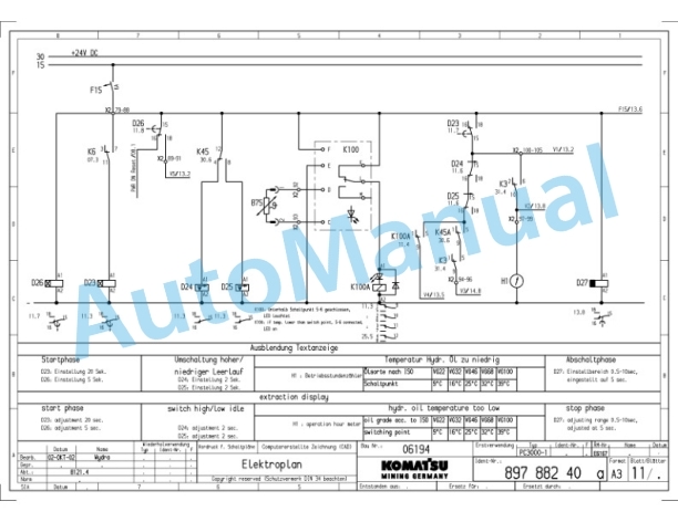
- 18.2.1. Electrical Circuit Diagrams 897 882 40 (1/40)
- 18.2.2. Electrical Circuit Diagrams 897 882 40 (2/40)
- 18.2.3. Electrical Circuit Diagrams 897 882 40 (3/40)
- 18.2.4. Electrical Circuit Diagrams 897 882 40 (4/40)
- 18.2.5. Electrical Circuit Diagrams 897 882 40 (5/40)
- 18.2.6. Electrical Circuit Diagrams 897 882 40 (6/40)
- 18.2.7. Electrical Circuit Diagrams 897 882 40 (7/40)
- 18.2.8. Electrical Circuit Diagrams 897 882 40 (8/40)
- 18.2.9. Electrical Circuit Diagrams 897 882 40 (9/40)
- 18.2.10. Electrical Circuit Diagrams 897 882 40 (10/40)
- 18.2.11. Electrical Circuit Diagrams 897 882 40 (11/40)
- 18.2.12. Electrical Circuit Diagrams 897 882 40 (12/40)
- 18.2.13. Electrical Circuit Diagrams 897 882 40 (13/40)
- 18.2.14. Electrical Circuit Diagrams 897 882 40 (14/40)
- 18.2.15. Electrical Circuit Diagrams 897 882 40 (15/40)
- 18.2.16. Electrical Circuit Diagrams 897 882 40 (16/40)
- 18.2.17. Electrical Circuit Diagrams 897 882 40 (17/40)
- 18.2.18. Electrical Circuit Diagrams 897 882 40 (18/40)
- 18.2.19. Electrical Circuit Diagrams 897 882 40 (19/40)
- 18.2.20. Electrical Circuit Diagrams 897 882 40 (20/40)
- 18.2.21. Electrical Circuit Diagrams 897 882 40 (21/40)
- 18.2.22. Electrical Circuit Diagrams 897 882 40 (22/40)
- 18.2.23. Electrical Circuit Diagrams 897 882 40 (23/40)
- 18.2.24. Electrical Circuit Diagrams 897 882 40 (24/40)
- 18.2.25. Electrical Circuit Diagrams 897 882 40 (25/40)
- 18.2.26. Electrical Circuit Diagrams 897 882 40 (26/40)
- 18.2.27. Electrical Circuit Diagrams 897 882 40 (27/40)
- 18.2.28. Electrical Circuit Diagrams 897 882 40 (28/40)
- 18.2.29. Electrical Circuit Diagrams 897 882 40 (29/40)
- 18.2.30. Electrical Circuit Diagrams 897 882 40 (30/40)
- 18.2.31. Electrical Circuit Diagrams 897 882 40 (31/40)
- 18.2.32. Electrical Circuit Diagrams 897 882 40 (32/40)
- 18.2.33. Electrical Circuit Diagrams 897 882 40 (33/40)
- 18.2.34. Electrical Circuit Diagrams 897 882 40 (34/40)
- 18.2.35. Electrical Circuit Diagrams 897 882 40 (35/40)
- 18.2.36. Electrical Circuit Diagrams 897 882 40 (36/40)
- 18.2.37. Electrical Circuit Diagrams 897 882 40 (37/40)
- 18.2.38. Electrical Circuit Diagrams 897 882 40 (38/40)
- 19. Section 14 Electronic Text Monitoring System
- 19.1. Table of Contents
- 19.1.1. Introduction
- 19.1.2. General
- 19.1.3. Function
- 19.1.4. Layout of Dash Board
- 19.1.5. Text Monitoring System
- 19.1.6. EFD Module, Function and Troubleshooting
Rate this product
You may also like
Komatsu Shop Manual PDF
$40.00

