


Komatsu Service Manual PDF
$40.00
Komatsu Service Manual PDF
Komatsu 4D94E, 4D94L, 4D98E Diesel Engine Forklift Truck Service Manual 4D94E-BE4
$40.00
Komatsu Service Manual PDF
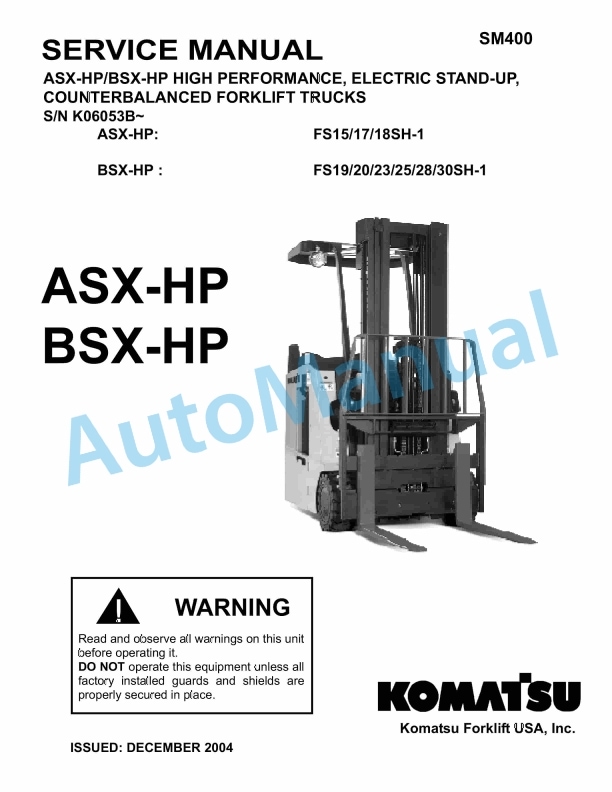
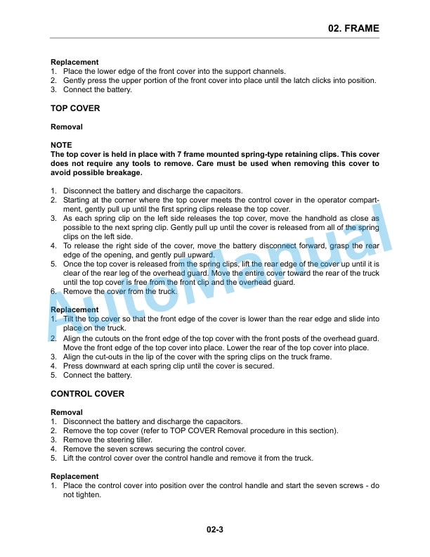
Komatsu ASX Stand-up Counterbalanced Electric Forklift Truck Service Manual SM401
$40.00
Komatsu Service Manual PDF
Komatsu G421, G422, G521, G522, G523 Transmission Service Manual 2975 413 M1
$40.00
