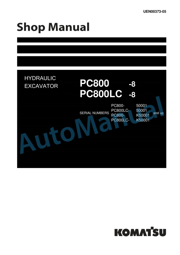
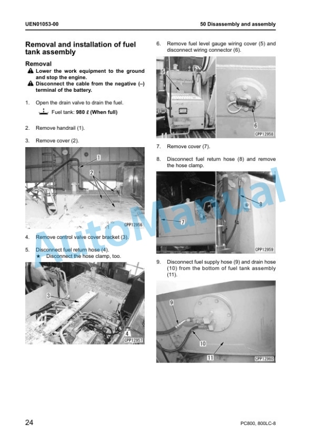
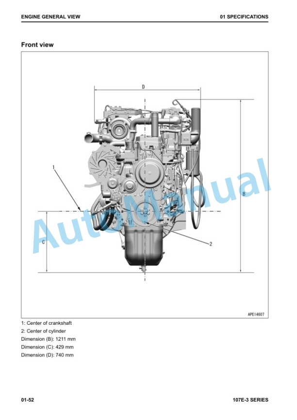
Komatsu PC800-8, PC800LC-8 Hydraulic Excavator Shop Manual UEN00373-05
$40.00
- Type Of Manual: Shop Manual
- Manual ID: UEN00373-05
- Format: PDF
- Size: 36.6MB
- Number of Pages: 1038
Category: Komatsu Shop Manual PDF
-
Model List:
- PC800-8 Hydraulic Excavator
- PC800LC-8 Hydraulic Excavator
- 1. Index and foreword
- 1.1. Index
- 1.1.1. Organization list of the shop manual
- 1.1.2. Table of contents
- 2. Index and foreword
- 2.1. Foreword and general information
- 2.1.1. Foreword and general information
- 3. Specification
- 3.1. Specification and technical data
- 3.1.1. Specification and technical data
- 4. Structure, function and maintenance standard
- 4.1. Engine and cooling system
- 4.1.1. Engine and cooling system
- 5. Structure, function and maintenance standard
- 5.1. Power train
- 5.1.1. Power train
- 6. Structure, function and maintenance standard
- 6.1. Undercarriage and frame
- 6.1.1. Undercarriage and frame
- 7. Structure, function and maintenance standard
- 7.1. Hydraulic system, Part 1
- 7.1.1. Hydraulic system, Part 1
- 8. Structure, function and maintenance standard
- 8.1. Hydraulic system, Part 2
- 8.1.1. Hydraulic system, Part 2
- 9. Structure, function and maintenance standard
- 9.1. Work equipment
- 9.1.1. Work equipment
- 10. Structure, function and maintenance standard
- 10.1. Cab and its attachments
- 10.1.1. Cab and its attachments
- 11. Structure, function and maintenance standard
- 11.1. Electrical system
- 11.1.1. Electrical system
- 12. Standard value table
- 12.1. Standard service value table
- 12.1.1. Standard service value table
- 13. Testing and adjusting
- 13.1. Testing and adjusting, Part 1
- 13.1.1. Testing and adjusting, Part 1
- 14. Testing and adjusting
- 14.1. Testing and adjusting, Part 2
- 14.1.1. Testing and adjusting, Part 2
- 15. Testing and adjusting
- 15.1. Testing and adjusting, Part 3
- 15.1.1. Testing and adjusting, Part 3
- 16. Testing and adjusting
- 16.1. Testing and adjusting, Part 4
- 16.1.1. Testing and adjusting, Part 4
- 17. Testing and adjusting
- 17.1. Testing and adjusting, Part 5
- 17.1.1. Testing and adjusting, Part 5
- 18. Troubleshooting
- 18.1. General information on troubleshooting
- 18.1.1. General information on troubleshooting
- 19. Troubleshooting
- 19.1. Troubleshooting by failure code (Display of code), Part 1
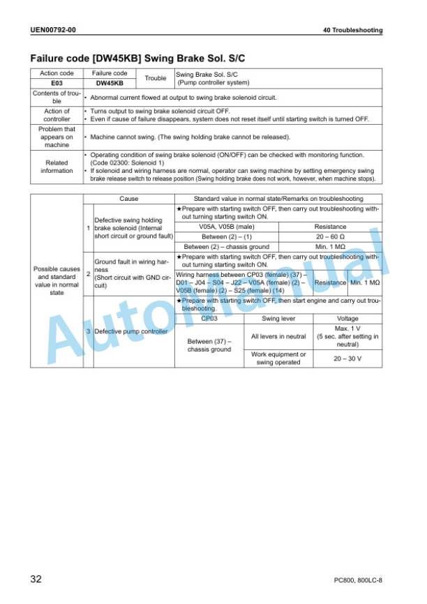
- 19.1.1. Troubleshooting by failure code (Display of code), Part 1
- 20. Troubleshooting
- 20.1. Troubleshooting by failure code (Display of code), Part 2
- 20.1.1. Troubleshooting by failure code (Display of code), Part 2
- 21. Troubleshooting
- 21.1. Troubleshooting by failure code (Display of code), Part 3
- 21.1.1. Troubleshooting by failure code (Display of code), Part 3
- 22. Troubleshooting
- 22.1. Troubleshooting of electrical system (Emode)
- 22.1.1. Troubleshooting of electrical system (Emode)
- 23. Troubleshooting
- 23.1. Troubleshooting of hydraulic and mechanical system (Hmode)
- 23.1.1. Troubleshooting of hydraulic and mechanical system (Hmode)
- 24. Troubleshooting
- 24.1. Troubleshooting of engine (Smode)
- 24.1.1. Troubleshooting of engine (Smode)
- 25. Disassembly and assembly
- 25.1. General information on disassembly and assembly
- 25.1.1. General information on disassembly and assembly
- 26. Disassembly and assembly
- 26.1. Engine and cooling system, Part 1
- 26.1.1. Engine and cooling system, Part 1
- 27. Disassembly and assembly
- 27.1. Engine and cooling system, Part 2
- 27.1.1. Engine and cooling system, Part 2
- 28. Disassembly and assembly
- 28.1. Power train
- 28.1.1. Power train
- 29. Disassembly and assembly
- 29.1. Undercarriage and frame
- 29.1.1. Undercarriage and frame
- 30. Disassembly and assembly
- 30.1. Hydraulic system
- 30.1.1. Hydraulic system
- 31. Disassembly and assembly
- 31.1. Work equipment
- 31.1.1. Work equipment
- 32. Disassembly and assembly
- 32.1. Cab and its attachments
- 32.1.1. Cab and its attachments
- 33. Disassembly and assembly
- 33.1. Electrical system
- 33.1.1. Electrical system
- 34. Diagrams and drawings
- 34.1. Hydraulic diagrams and drawings
- 34.1.1. Hydraulic circuit diagram
- 35. Diagrams and drawings
- 35.1. Electrical diagrams and drawings
- 35.1.1. Electrical circuit diagram (1/5)
- 35.1.2. Electrical circuit diagram (2/5)
- 35.1.3. Electrical circuit diagram (3/5)
- 35.1.4. Electrical circuit diagram (4/5)
- 35.1.5. Electrical circuit diagram (5/5)
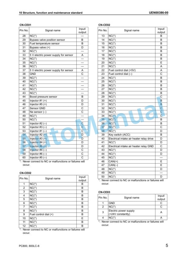
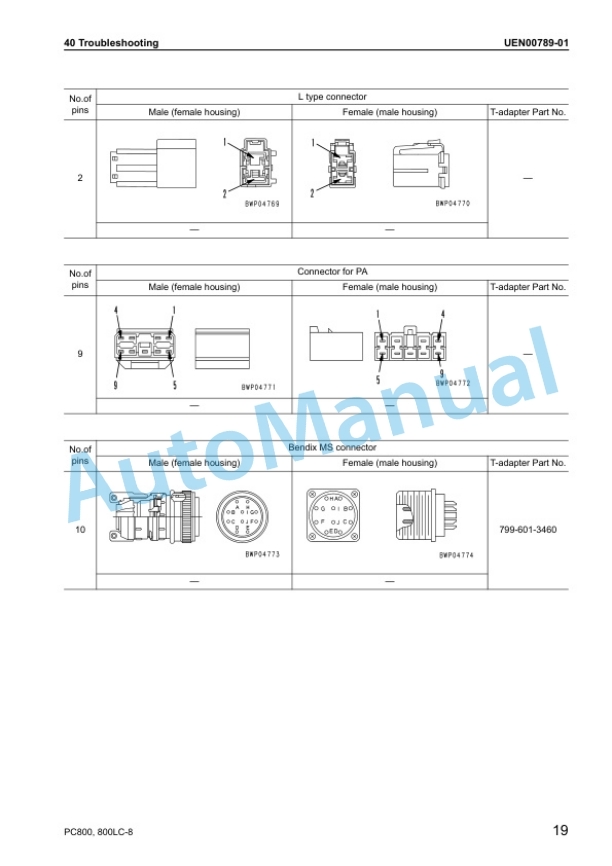
- 35.1.6. Connector arrangement diagram
Rate this product
You may also like

