No products in the cart.
Return to shop
$50.00
Komatsu Shop Manual PDF
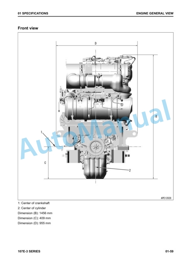
Komatsu 107E-3 Series Engine Shop Manual SEN06502-20
Komatsu 102 Series Diesel Engine Shop Manual SM140
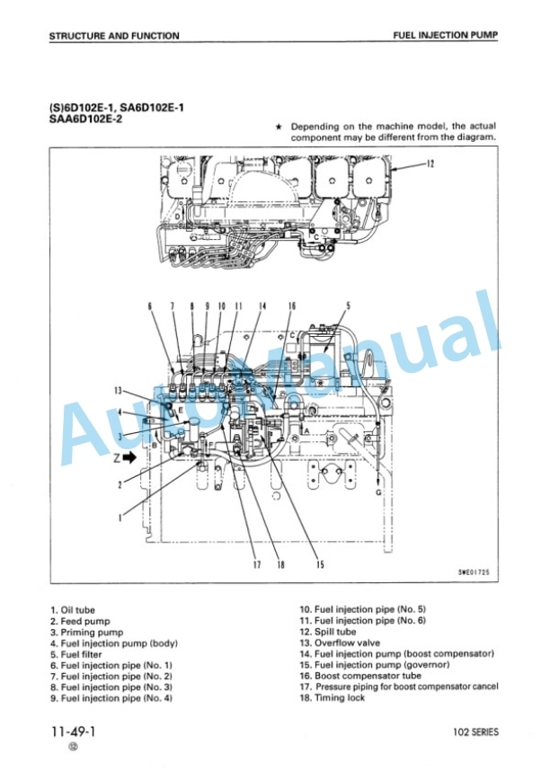
Komatsu 102 Series Diesel Engine Shop Manual SEBM010025
Komatsu 102 Series Diesel Engine Shop Manual SM104
Komatsu 107E-2 Series Engine Shop Manual SEN05623-09
Komatsu 102 Series Diesel Engine Shop Manual SEBM010026
Komatsu 105 Series Diesel Engine Shop Manual SEBE6130A04
Komatsu 108 Series Diesel Engine Shop Manual SEBE62210103
Komatsu 107E-3 Series Engine Shop Manual SEN06502-21
Komatsu 102 Series Diesel Engine Shop Manual YEBM200101


