Skip to content
Auto ManualAuto Manual
  • Login
  • $0.00
    • No products in the cart.

      Return to shop

  • Cart

    No products in the cart.

    Return to shop

  • Category
  • Menu
  • About us
  • Shop
  • News
  • Contact Us
  • John Deere
  • Claas
    • Claas Assembly Instruction PDF
    • Claas Operator Manual PDF
    • Claas Repair Manual PDF
    • Claas Service Information PDF
    • Claas Technical System PDF
  • Grove
  • Jungheinrich
  • Komatsu
  • Kubota
  • Manitowoc
  • New Holland
  • Yale
  • Yanmar
Support
Email
admin@automanual.net
Follow us
Home / Bomag / Bomag Service Manual PDF
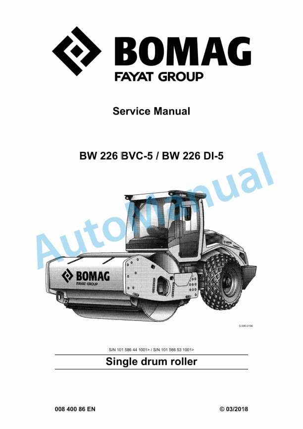
bomag bw 226 bvc 5 bw 226 di 5 single drum roller service manual 00840086 1
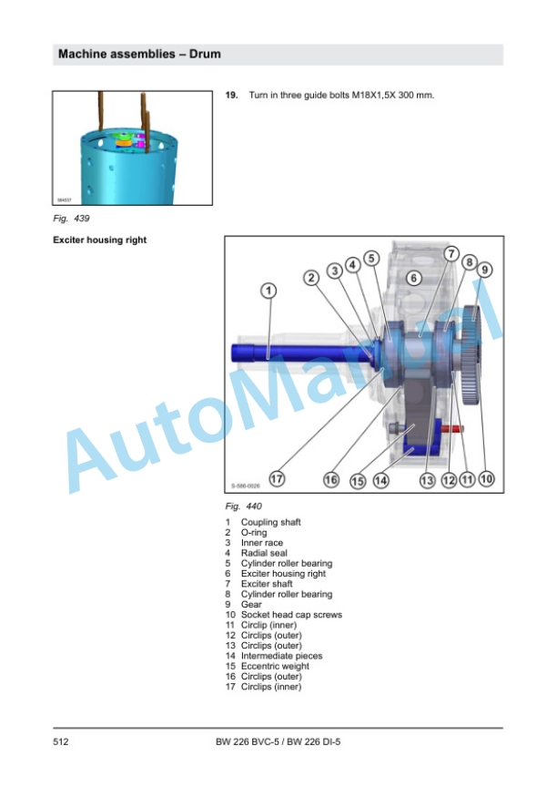
bomag bw 226 bvc 5 bw 226 di 5 single drum roller service manual 00840086 2
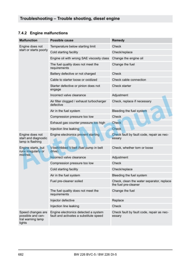
bomag bw 226 bvc 5 bw 226 di 5 single drum roller service manual 00840086 3
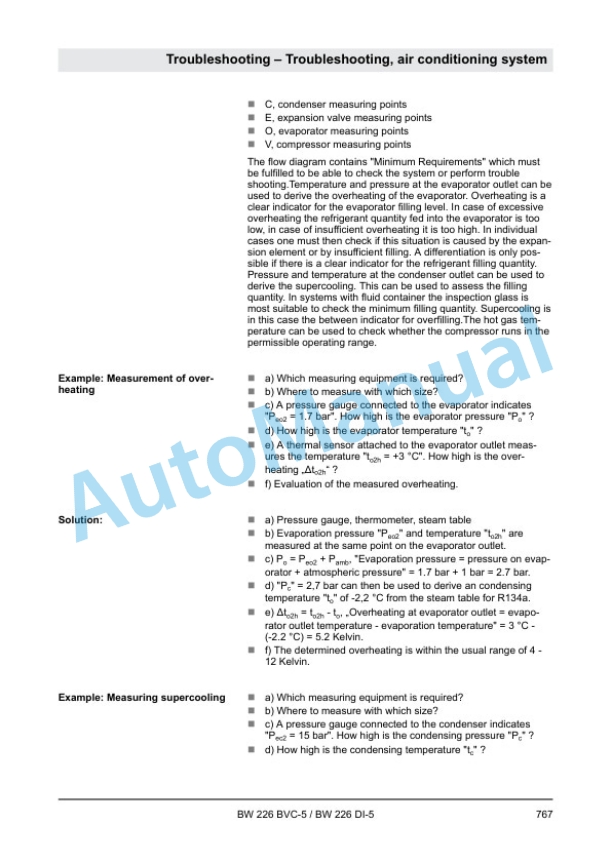
bomag bw 226 bvc 5 bw 226 di 5 single drum roller service manual 00840086 4
bomag bw 226 bvc 5 bw 226 di 5 single drum roller service manual 00840086 5

Bomag BW 226 BVC-5, BW 226 DI-5 Single Drum Roller Service Manual 00840086

$30.00

  • Type Of Manual: Service Manual
  • Manual ID: 00840086
  • Format: PDF
  • Size: 86.4MB
  • Number of Pages: 1022
  • Serial Number:
    101586441001 and up
    101586531001 and up
Category: Bomag Service Manual PDF
Product Categories
  • All Product (0)
  • Alo (0)
    • Alo Service Manual PDF (0)
  • Bomag (3931)
    • Bomag Operator Manual PDF (53)
    • Bomag Other Manual PDF (0)
    • Bomag Parts Manual PDF (9)
    • Bomag Repair Manual PDF (1)
    • Bomag Service Manual PDF (1367)
    • Bomag Spare Parts Catalogue PDF (2501)
  • Briggs and Stratton (0)
    • Briggs and Stratton Repair Manual PDF (0)
  • CASE (0)
    • CASE Operator Manual PDF (0)
    • CASE Other Manual PDF (0)
    • CASE Parts Catalog PDF (0)
    • CASE Service Manual PDF (0)
    • CASE Workshop Manual PDF (0)
  • Claas (6622)
    • Claas Assembly Instruction PDF (741)
    • Claas Operator Manual PDF (2393)
    • Claas Repair Manual PDF (1660)
    • Claas Service Information PDF (20)
    • Claas Technical System PDF (1808)
  • Clark (0)
    • Clark Operator Manual PDF (0)
    • Clark Other Manual PDF (0)
    • Clark Parts Manual PDF (0)
    • Clark Service Manual PDF (0)
    • Clark Workshop Manual PDF (0)
  • CMI Corporation (0)
    • CMI Corporation Parts Manual PDF (0)
    • CMI Corporation Service Manual PDF (0)
  • CNH (0)
    • CNH Operator Manual PDF (0)
    • CNH Repair Manual PDF (0)
    • CNH Service Manual PDF (0)
  • Doosan (0)
    • Doosan Operator Manual PDF (0)
    • Doosan Service Manual PDF (0)
  • Dynapac (0)
    • Dynapac Spare Parts Catalogue PDF (0)
  • Eaton Hydraulics Division (0)
    • Eaton Hydraulics Division Repair Manual PDF (0)
  • Fiat Hitachi (0)
    • Fiat Hitachi Service Manual PDF (0)
  • Fiatagri (0)
    • Fiatagri Operator Manual PDF (0)
    • Fiatagri Service Manual PDF (0)
    • Fiatagri Workshop Manual PDF (0)
  • Fiatallis (0)
    • Fiatallis Operator Manual PDF (0)
    • Fiatallis Other Manual PDF (0)
    • Fiatallis Repair Manual PDF (0)
    • Fiatallis Service Manual PDF (0)
  • Flexi Coil (0)
    • Flexi Coil Repair Manual PDF (0)
    • Flexi Coil Service Manual PDF (0)
  • Ford New Holland (0)
    • Ford New Holland Operator Manual PDF (0)
    • Ford New Holland Other Manual PDF (0)
    • Ford New Holland Repair Manual PDF (0)
    • Ford New Holland Service Manual PDF (0)
  • FPT Powertrain Technologies (0)
    • FPT Powertrain Technologies Service Manual PDF (0)
  • Grove (3764)
    • Grove Parts List PDF (3764)
  • Hesston (0)
    • Hesston Operator Manual PDF (0)
  • HINO (1)
  • Hypac (0)
    • Hypac Spare Parts Catalogue PDF (0)
  • IMT (198)
  • John Deere (580)
    • John Deere Operation and Test Manual PDF (24)
      • John Deere Wiring Diagrams PDF (24)
    • John Deere Parts Catalog PDF (371)
    • John Deere Repair Technical Manual PDF (165)
  • Jungheinrich (3746)
    • Jungheinrich Spare Parts Manual PDF (3744)
  • Kemper (0)
    • Kemper Repair Manual PDF (0)
  • Kobelco (0)
    • Kobelco Repair Manual PDF (0)
    • Kobelco Service Manual PDF (0)
  • Kohler (0)
    • Kohler Service Manual PDF (0)
  • Komatsu (9889)
    • Komatsu Operation and Maintenance Manual PDF (4958)
    • Komatsu Other Manual PDF (0)
    • Komatsu Parts Manual PDF (2021)
    • Komatsu Service Manual PDF (64)
    • Komatsu Shop Manual PDF (2846)
  • Krupp (58)
    • Krupp Parts List PDF (58)
  • Kubota (2290)
    • Kubota Operators Manual PDF (95)
    • Kubota Other Manual PDF (10)
    • Kubota Parts Manual PDF (1817)
    • Kubota Service Manual PDF (9)
    • Kubota Workshop Manual PDF (359)
  • Liebherr (2)
  • Linde (0)
    • Linde Operator Manual PDF (0)
    • Linde Parts Manual PDF (0)
    • Linde Workshop Manual PDF (0)
  • Manitowoc (998)
    • Manitowoc Parts Manual PDF (998)
  • Miller (0)
    • Miller Repair Manual PDF (0)
    • Miller Service Manual PDF (0)
  • New Holland (2809)
    • New Holland Operator Manual PDF (853)
    • New Holland Parts Catalog PDF (31)
    • New Holland Repair Manual PDF (17)
    • New Holland Service Manual PDF (1852)
    • New Holland Workshop Manual PDF (55)
    • Service Manual PDF (1)
  • Other Language (0)
  • Other Manual (0)
    • Superior Engineering Service Manual PDF (0)
  • Porsche (5)
  • Sperry New Holland (0)
    • Sperry New Holland Operator Manual PDF (0)
    • Sperry New Holland Parts Catalog PDF (0)
    • Sperry New Holland Service Manual PDF (0)
  • Stehr (0)
    • Stehr Spare Parts Catalogue PDF (0)
  • Stow (0)
    • Stow Spare Parts Catalogue PDF (0)
  • TCM (1)
  • Terex (0)
    • Terex Service Manual PDF (0)
  • Versatile (0)
    • Versatile Operator Manual PDF (0)
    • Versatile Service Manual PDF (0)
  • Yale (585)
    • Yale Service Manual PDF (585)
  • Yanmar (0)
    • Yanmar Service Manual PDF (0)
  • Zahnradfabrik (0)
    • Zahnradfabrik Repair Manual PDF (0)
  • Model List:

    • BW 226 BVC-5 Single Drum Roller
    • BW 226 DI-5 Single Drum Roller
  • 1. Table of contents
  • 2. General
  • 2.1. Introduction
  • 2.2. Concerning your safety
  • 2.2.1. Basic prerequisites
  • 2.2.2. Definition of responsible persons
  • 2.2.3. Fundamentals for safe operation
  • 2.2.4. Handling fuels and lubricants
  • 2.2.5. Load/transport the machine
  • 2.2.6. Startup procedure
  • 2.2.7. Driving the machine working operation
  • 2.2.8. Refuelling
  • 2.2.9. Emergency procedures
  • 2.2.10. Maintenance work
  • 2.2.11. Repair
  • 2.2.12. Signage
  • 2.3. Maintenance and repair
  • 2.3.1. Notes on repair
  • 2.3.2. Preliminary remarks and safety notes
  • 2.3.3. Preparations / concluding work
  • 2.3.4. Parking the machine in secured condition
  • 3. Technical data
  • 3.1. Technical data, BW 226 BVC5
  • 3.1.1. Technical data
  • 3.2. Technical data, BW 226 DI5
  • 3.2.1. Technical data
  • 3.3. Additional technical data
  • 3.4. Terms and basis of calculation
  • 3.5. Fuels and lubricants
  • 3.5.1. Engine oil
  • 3.5.2. Fuel
  • 3.5.3. Coolant
  • 3.5.4. Hydraulic oil
  • 3.5.5. Gear oil SAE 75W90
  • 3.5.6. Gear oil SAE 80W140
  • 3.6. List of fuels and lubricants
  • 4. Overview of machine
  • 4.1. General information
  • 4.1.1. BCM 05
  • 4.1.2. BCM start
  • 4.1.3. BCM net
  • 4.1.4. BOMAG Telematic
  • 4.2. Electric systems
  • 4.3. Hydraulic system
  • 4.4. Machine assemblies
  • 4.4.1. Diesel engine
  • 4.4.2. Drum
  • 4.4.3. Air conditioning
  • 4.4.4. Auxiliary heating, AIRTRONIC
  • 5. Electric systems
  • 5.1. Basic principles
  • 5.1.1. Measuring method
  • 5.1.2. Understanding electric circuit diagrams
  • 5.1.3. Telemecanique switch
  • 5.1.4. Deutsch plug, series DT and DTM
  • 5.2. Overview of electric system
  • 5.2.1. Central electrics
  • 5.2.2. Operators stand
  • 5.2.3. Wiring
  • 5.2.4. CAN BUS overview
  • 5.2.5. Table of fuels and lubricants
  • 5.3. Starting the engine with jump leads
  • 5.4. Fuse assignment
  • 5.4.1. Notes on safety
  • 5.4.2. Central electrics
  • 5.4.3. Main fuses
  • 5.4.4. Control console cabin
  • 5.5. Central electrics
  • 5.6. Description of electrical components
  • 5.6.1. Control console cabin
  • 5.6.2. Acceleration transducer, B62 B171
  • 5.6.3. Differential pressure switch for hydraulic oil filter, B21
  • 5.6.4. Air filter vacuum switch, B03
  • 5.6.5. Sensor, water in fuel, B124
  • 5.6.6. Float switch coolant tank, B55
  • 5.6.7. Level sensor in diesel tank (R03)
  • 5.6.8. Charge control light
  • 5.6.9. Electric module, A108
  • 5.7. Training of electric system
  • 5.7.1. Electrics training machine control
  • 5.7.2. Electrics training metrology control
  • 5.8. Inspection and maintenance work
  • 5.8.1. Maintenance Table
  • 5.8.2. Every 500 operating hours
  • 5.8.3. As required
  • 6. Hydraulic system
  • 6.1. Basic principles
  • 6.1.1. Open and closed hydraulic circuit
  • 6.1.2. Swash plate principle, pump
  • 6.1.3. Swash plate principle, motor
  • 6.1.4. External gear pumps
  • 6.2. Overview of hydraulics
  • 6.3. Description of hydraulic components
  • 6.3.1. Travel / vibration pump, H1
  • 6.3.2. Travel motor, H1
  • 6.3.3. Vibration motor A2FM
  • 6.3.4. Steering valve
  • 6.3.5. Diaphragm type pressure accumulator
  • 6.3.6. Slewing motor
  • 6.4. Description of hydraulic circuits
  • 6.4.1. Charge circuit
  • 6.4.2. Travel circuit
  • 6.4.3. Vibration circuit
  • 6.4.4. Steering circuit
  • 6.4.5. Bypass flow filter
  • 6.5. Flushing and bleeding
  • 6.5.1. Flushing general
  • 6.5.2. Drum drive
  • 6.5.3. Axle drive
  • 6.5.4. Vibration circuit
  • 6.5.5. Bleeding the travel circuit
  • 6.5.6. Bleeding the vibration circuit
  • 6.6. Inspection and maintenance work
  • 6.6.1. Maintenance Table
  • 6.6.2. Checks prior to start up
  • 6.6.3. Every 500 operating hours
  • 6.6.4. Every 1000 operating hours
  • 6.6.5. Every 2000 operating hours
  • 7. Machine assemblies
  • 7.1. Diesel engine
  • 7.1.1. Overviews
  • 7.1.2. Lubrication oil circuit TCD 4.1 / 6.1
  • 7.1.3. Coolant circuit TCD 4.1 / 6.1
  • 7.1.4. Common Rail System (CRS)
  • 7.1.5. Wastegate charge pressure controller
  • 7.1.6. Exhaust gas recirculation
  • 7.1.7. Engine electrics
  • 7.1.8. Inspection and maintenance work
  • 7.2. BOMAG, Variocontrol
  • 7.2.1. Variocontrol
  • 7.2.2. Vibration circuit
  • 7.2.3. Potentiometer on slewing motor, B97
  • 7.3. Drum
  • 7.3.1. Overview drum
  • 7.3.2. Removing the exciter unit
  • 7.3.3. Installing the exciter unit
  • 7.3.4. Assembling the vibrator unit
  • 7.3.5. Changing the rubber buffers, adjusting the pretension
  • 7.3.6. Smooth drum scraper installation and removal
  • 7.3.7. Pad foot scraper installation and removal
  • 7.3.8. Padfoot shell installation and removal
  • 7.3.9. Inspection and maintenance work
  • 7.4. Oscillating articulated joint
  • 7.4.1. Overview
  • 7.4.2. Dismantling the oscillating articulated joint
  • 7.4.3. Assembly of oscillating articulated joint
  • 7.5. Drive axle
  • 7.5.1. Drive axle
  • 7.5.2. Checks prior to start up
  • 7.5.3. Every 250 operating hours
  • 7.5.4. Every 1000 operating hours
  • 7.5.5. As required
  • 7.6. Air conditioning
  • 7.6.1. Overview of air conditioning system
  • 7.6.2. Physical principles
  • 7.6.3. Refrigerant R134a
  • 7.6.4. Compressor oil / refrigeration oil
  • 7.6.5. Working principle of the air conditioning system
  • 7.6.6. Monitoring devices
  • 7.6.7. Description of components
  • 7.6.8. Compressor
  • 7.6.9. Emptying in case of repair
  • 7.6.10. Drying and evacuation
  • 7.6.11. Filling instructions
  • 7.6.12. Steam table for R134a
  • 7.6.13. Inspection and maintenance work
  • 7.7. Auxiliary heating, AIRTRONIC
  • 7.7.1. Overview
  • 7.7.2. Inspection and maintenance work
  • 7.8. Cabin assembly
  • 7.8.1. Safety
  • 7.8.2. Preparations
  • 7.8.3. Cabin assembly
  • 7.8.4. Final function tests and checks
  • 7.9. ROPS/FOPS assembly
  • 7.9.1. Safety
  • 7.9.2. Preparations
  • 7.9.3. ROPS/FOPS assembly
  • 7.9.4. Final work
  • 8. Troubleshooting
  • 8.1. Preliminary remarks
  • 8.2. Emergency procedures
  • 8.2.1. Actuating the emergency stop switch
  • 8.2.2. Disconnecting the battery
  • 8.2.3. Emergency exit
  • 8.2.4. Towing the machine
  • 8.2.5. After towing
  • 8.3. Troubleshooting, electrical systems
  • 8.3.1. Preliminary remarks
  • 8.3.2. Starting the engine with jump leads
  • 8.3.3. Servicing the battery, checking the main battery isolation
  • 8.3.4. Fuse assignment
  • 8.3.5. ESX, checking the electric power supply
  • 8.3.6. Diagnostics concept
  • 8.4. Trouble shooting, diesel engine
  • 8.4.1. Starting the engine with jump leads
  • 8.4.2. Engine malfunctions
  • 8.4.3. DTC fault code list, EMR4
  • 8.5. Trouble shooting, hydraulics
  • 8.5.1. Insufficient hydraulic power
  • 8.5.2. Trouble shooting axial piston pumps
  • 8.5.3. Trouble shooting axial piston motors
  • 8.5.4. Fault table hydraulic components
  • 8.6. Troubleshooting, air conditioning system
  • 8.6.1. Trouble shooting in refrigerant circuit, basic principles
  • 8.6.2. Trouble shooting procedure
  • 8.6.3. Leak test
  • 8.6.4. Checking the magnetic clutch
  • 8.7. Troubleshooting, auxiliary heating
  • 8.7.1. Control and safety elements
  • 8.7.2. Trouble shooting
  • 8.7.3. Diagnostics with the module clock
  • 8.7.4. Check the fuel supply
  • 8.7.5. Circuit diagram, AIRTRONIC D2/D4
  • 8.7.6. Fault code, AIRTRONIC D2/D4
  • 9. Special tools
  • 9.1. Special tools, electrics
  • 9.2. Special tools, hydraulic system
  • 9.2.1. Special tools, tests and adjustments
  • 9.2.2. Special tools for flushing
  • 9.3. Special tools for drum
  • 9.4. List of special tools
  • 10. Index
  • 11. Appendix
  • 11.1. A Circuit diagrams
  • 11.1.1. Circuit diagram 354
  • 11.1.2. Circuit diagram 520
  • 11.1.3. Hydraulic diagram 480
Rate this product
You may also like
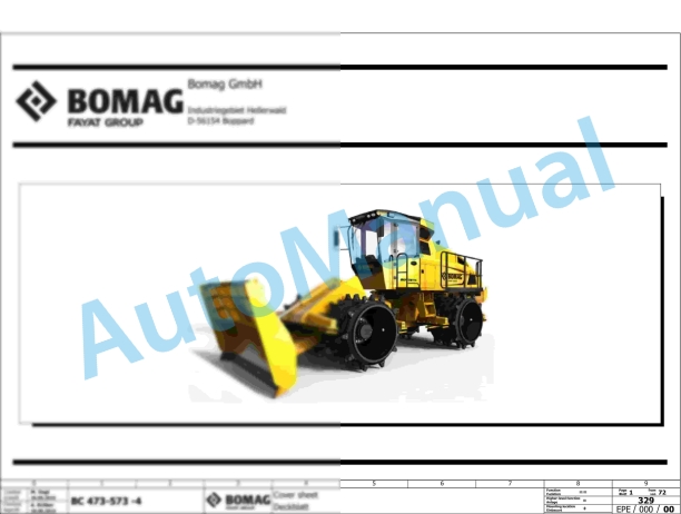
Bomag BC 473 RB-5 Refuse Compactor Electric, Hydraulic Schematics Diagram 101930211001 - 101930219999

Bomag Service Manual PDF

Bomag BC 473 RB-5 Refuse Compactor Electric, Hydraulic Schematics Diagram 101930211001 – 101930219999

$30.00
Add to cart
Bomag BC 1172 RB-2 Refuse Compactor Electric, Hydraulic Schematics Diagram 101570851022 - 101570859999

Bomag Service Manual PDF

Bomag BC 1172 RB-2 Refuse Compactor Electric, Hydraulic Schematics Diagram 101570851022 – 101570859999

$30.00
Add to cart
Bomag BC 473 RS-5 Refuse Compactor Electric, Hydraulic Schematics Diagram 101930221001 - 101930229999

Bomag Service Manual PDF

Bomag BC 473 RS-5 Refuse Compactor Electric, Hydraulic Schematics Diagram 101930221001 – 101930229999

$30.00
Add to cart
Bomag BC 462 EB Refuse Compactor Electric, Hydraulic Schematics Diagram 101930061001 - 101930061001

Bomag Service Manual PDF

Bomag BC 462 EB Refuse Compactor Electric, Hydraulic Schematics Diagram 101930061001 – 101930061001

$30.00
Add to cart
Bomag BC 1172 RB-3 Refuse Compactor Electric, Hydraulic Schematics Diagram 101570891001 - 101570891018

Bomag Service Manual PDF

Bomag BC 1172 RB-3 Refuse Compactor Electric, Hydraulic Schematics Diagram 101570891001 – 101570891018

$30.00
Add to cart
Bomag BC 472 RS Refuse Compactor Electric, Hydraulic Schematics Diagram 101930011002 - 101930011011

Bomag Service Manual PDF

Bomag BC 472 RS Refuse Compactor Electric, Hydraulic Schematics Diagram 101930011002 – 101930011011

$30.00
Add to cart
Bomag BC 473 RS-4 Refuse Compactor Electric, Hydraulic Schematics Diagram 101930091001 - 101930099999

Bomag Service Manual PDF

Bomag BC 473 RS-4 Refuse Compactor Electric, Hydraulic Schematics Diagram 101930091001 – 101930099999

$30.00
Add to cart
Bomag BC 571 RB Refuse Compactor Electric, Hydraulic Schematics Diagram 101570621033 - 101570621062

Bomag Service Manual PDF

Bomag BC 571 RB Refuse Compactor Electric, Hydraulic Schematics Diagram 101570621033 – 101570621062

$30.00
Add to cart
Bomag BC 572 RB-2 Refuse Compactor Electric, Hydraulic Schematics Diagram 101570641001 - 101570641054

Bomag Service Manual PDF

Bomag BC 572 RB-2 Refuse Compactor Electric, Hydraulic Schematics Diagram 101570641001 – 101570641054

$30.00
Add to cart
Bomag BC 472 RS Refuse Compactor Electric, Hydraulic Schematics Diagram 101930051001 - 101930051010

Bomag Service Manual PDF

Bomag BC 472 RS Refuse Compactor Electric, Hydraulic Schematics Diagram 101930051001 – 101930051010

$30.00
Add to cart
auto manual
    Links of interest
    • About us
    • Refund and Returns Policy
    • Terms & Conditions
    • Shipping Policy
    • Privacy Policy
    • Contact Us
    Product tags
    Agricultural Automotive Crane Forklift Heavy Construction
© All rights reserved. 2023
Copyright 2025 © automanual.net
  • Category
  • Menu
  • About us
  • Shop
  • News
  • Contact Us
  • John Deere
  • Claas
    • Claas Assembly Instruction PDF
    • Claas Operator Manual PDF
    • Claas Repair Manual PDF
    • Claas Service Information PDF
    • Claas Technical System PDF
  • Grove
  • Jungheinrich
  • Komatsu
  • Kubota
  • Manitowoc
  • New Holland
  • Yale
  • Yanmar
Login

Lost your password?