- Claas
- Grove
- New Holland
- Komatsu
- Kubota
- John Deere
- Linde
- Bomag
- CASE
- Clark
- JCB
- Jungheinrich
- Linde
- Yale
- Yanmar
- Manitou
- Manitowoc
- CNH
- Doosan
- Fiatagri
- Fiatallis
- Fiatallis Other Manual PDF
- Flexi Coil
- Ford New Holland
- Ford New Holland Other Manual PDF
- Huyndai
- Hypac
- Hyster
- Hyster Service Manual PDF
- Isuzu
- Kobelco
- Kohler
- Krupp
- Lombardini
- Mahindra
- Nuvera
- Perkins
- Sperry New Holland
- Utilev
- Versatile
- ZF


Clark C15s D-L, C 18s D-L, C 20s D-L, C15s C-L, C 18s C-L, C 20s C-L Service Manual SM-1066
$30.00
- Type Of Manual: Service Manual
- Manual ID: SM-1066
- Format: PDF
- Size: 44.3MB
- Number of Pages: 949
- Serial Number:
Hyundai (T4), Mitsubishi (T3), Yanmar (T3)
Category: Clark Service Manual PDF
-
Model List:
- C15s D-L
- C 18s D-L
- C 20s D-L
- C15s C-L
- C 18s C-L
- C 20s C-L
- 1. SM1066
- 2. CONTENTS
- 3. GROUP SA SAFE MAINTENANCE
- 3.1. Section 1 Safety
- 3.2. Section 2 Lifting, Jacking, and Blocking the Truck
- 3.3. Section 3 Towing
- 4. GROUP PS PERIODIC SERVICE
- 4.1. Section 1 Maintenance Schedules
- 4.2. Section 2 The Planned Maintenance Program
- 5. GROUP 00 (D4TNV88) DIESEL ENGINE (4TNV88)
- 5.1. Section 0 SAFETY
- 5.2. Section 1 GENERAL
- 5.3. Section 2 Inspection and Adjustment
- 5.4. Section 3 Troubleshooting
- 5.5. Section 4 Disassembly, Inspection and Reassembly of Engines
- 5.6. Section 5 LUBRICATION SYSTEM
- 5.7. Section 6 COOLING SYSTEM
- 5.8. Section 7 FUEL INJECTION PUMP/GOVERNOR
- 5.9. Section 8 ALTERNATOR
- 5.10. Section 9 ELECTRIC WIRING
- 5.11. Section 10 SERVICE STANDARDS
- 5.12. Section 11 TIGHTENING TORQUE for BOLTS and NUTS
- 6. GROUP 00 (LMMC) ENGINE (4G63 GAS/LPG)
- 6.1. Section 1 Engine Specifications (4G63 Gas/LPG Engine)
- 6.2. Section 2 Engine Troublshooting (4G63 Gas/LPG Engine)
- 6.3. Section 3 Engine Oil and Filter (4G63 Gas/LPG Engine)
- 6.4. Section 4 Engine TuneUp (4G63 Gas/LPG Engine)
- 6.5. Section 5 RPM, Vacuum, and Stall Tests (4G63 Gas/LPG Engine)
- 6.6. Section 6 Compression Checks (4G63 Gas/LPG Engine)
- 6.7. Section 7 Engine Removal and Replacement (4G63 Gas/LPG Engine)
- 6.8. Section 8 Engine Overhaul (4G63 Gas/LPG Engine)
- 6.9. Section 9 Ignition System (4G63 Gas/LPG Engine)
- 7. GROUP 00 (LHMC) ENGINE (HMC THETA 2.4 LPG)
- 7.1. Section 1 General Information (HMC THETA 2.4 LPG)
- 7.2. Section 2 Specification and Troubleshooting (HMC THETA 2.4 LPG)
- 7.3. Section 3 Disassembly and Reassembly (HMC THETA 2.4 LPG)
- 7.4. Section 4 Lubrication System (HMC THETA 2.4 LPG)
- 7.5. Section 5 Electrical System (HMC THETA 2.4 LPG)
- 7.6. Section 6 Emission Control System (HMC THETA 2.4 LPG)
- 8. GROUP 01 ENGINE COOLING SYSTEM
- 8.1. Section 1 Engine Cooling System Specifications and Description
- 8.2. Section 2 Engine Cooling System Troubleshooting
- 8.3. Section 3 Engine Cooling SystemTesting and Maintenance
- 8.4. Section 4 Engine Cooling System and Alternator Belt Service
- 8.5. Section 5 Radiator Removal and Replacemant
- 9. GROUP 02 (LMMC,TIER3) MI07 LP SYSTEM (4G63)
- 9.1. Section 0 REGULATORY COMPLIANCE
- 9.2. Section 1 LPG SYSTEM OVERVIEW
- 9.3. Section 2 GASOLINE ENGINES
- 9.4. Section 3 SPECIFICATIONS
- 9.5. Section 4 RECOMMENDED MAINTENANCE
- 9.6. Section 5 INSTALLATION PROCEDURES
- 9.7. Section 6 TESTS AND ADJUSTMENTS
- 9.8. Section 7 BASIC TROUBLESHOOTING
- 9.9. Section 8 ADVANCED DIAGNOSTICS
- 9.10. Section 9 PARTS DESCRIPTION
- 10. GROUP 02 (LHMC THETA 2.4) LPG FUEL SYSTEM
- 10.1. Section 1 General Warnings
- 10.2. Section 2 Introduction
- 10.3. Section 3 Base Engine
- 10.4. Section 4 Fuel System
- 10.5. Section 5 Recommended Maintenance
- 10.6. Section 6 Diagnostic Trouble Codes (DTC)
- 10.7. Section 7 Troubleshooting
- 10.8. Section 8 Appendicies
- 10.9. Section 9 Diagnostic Service Tool
- 11. GROUP 03 INTAKE AND EXHAUST SYSTEM
- 11.1. Section 1 Intake and Exhaust Systems Specifications and Description
- 11.2. Section 2 Intake System Troubleshooting
- 11.3. Section 3 Intake System Service
- 11.4. Section 4 Exhaust Systems
- 12. GROUP 06 TRANSAXLE (TA12A1 TRANSAXLE) C1520s
- 12.1. Section 1 Transaxle Specifications and Description
- 12.2. Section 2 Transaxle Disassembly
- 12.3. Section 3 Transaxle Reassembly
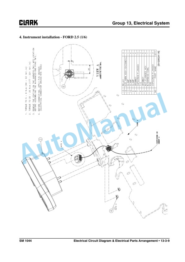
- 13. GROUP 13 ELECTRICAL SYSTEM
- 13.1. Section 1 Cautions for working on the electrical system
- 13.2. Section 2 Electrical system Specifications and features
- 13.3. Section 3 Electrical Circuit Diagram Electrical Parts Arrangement
- 13.4. Section 4 Instrument Pod
- 13.5. Section 5 Electrical Components Specification and Operation
- 13.6. Section 6 Troubleshooting of Electrical System
- 14. GROUP 22 WHEELS AND TIRES
- 14.1. Section 1 Wheels and Tires Specifications and Description
- 14.2. Section 2 Cushion Wheels and Tires
- 14.3. Section 3 Pneumatic Wheels and Tires
- 15. GROUP 23 BRAKE SYSTEM
- 15.1. Section 1 Braking / Inching System Specifications and Description
- 15.2. Section 2 Service Brake Troubleshooting
- 15.3. Section 3 Brake / Inching Pedals and Linkages Adjustments
- 15.4. Section 4 Brake System Bleeding
- 15.5. Section 5 Brake Master Cylinder Service
- 15.6. Section 6 Service Brake Adjustment and Overhaul
- 15.7. Section 7 Parking Brake Service
- 16. GROUP 25 STEERING COLUMN AND GEAR
- 16.1. Section 1 Steering System Specifications and Description
- 16.2. Section 2 Steering System Troubleshooting
- 16.3. Section 3 Steering Column and Component Removal and Replacement
- 16.4. Section 4 Stering System Relief Pressure Check and Adjustment
- 16.5. Section 5 Steering Gear Overhaul
- 17. GROUP 26 STEER AXLE
- 17.1. Section 1 Steer Axle Specifications and Description
- 17.2. Section 2 Steer Axle Wheel Bearing Maintenance and Adjustment
- 17.3. Section 3 Steer Axle Removal and Replacement
- 17.4. Section 4 Steer Axle Overhaul
- 17.5. Section 5 Steer Cylinder Removal and Replacement
- 17.6. Section 6 Steer Cylinder Overhaul
- 18. GROUP 29 HYDRAULIC SUMP, FILTERS, AND PUMP
- 18.1. Section 1 Hydraulic Sump, Filters, and Pump Specifications and Description
- 18.2. Section 2 Main Hydraulic Pump Troubleshooting
- 18.3. Section 3 Hydraulic Filters and Fluid Maintenance and Change
- 18.4. Section 4 Hydraulic Pump Removal and Replacement
- 18.5. Section 5 Hydraulic Pump Overhaul (Jinsung Pump)
- 19. GROUP 30 HYDRAULIC CONTROL VALVE/LIFT CIRCUIT
- 19.1. Section 1 Hydraulic Control Valve/Lift Circuit Specifications and Description
- 19.2. Section 2 Hydraulic System Schematics
- 19.3. Section 3 Hydraulic System Troubleshooting
- 19.4. Section 4 Hydraulic System Pressure Checks and Adjustments
- 19.5. Section 5 Hydraulic Control Valve Removal and Replacement
- 19.6. Section 6 Disassembly and Assembly
- 19.7. Section 7 Testing of Hydraulic Valve
- 20. GROUP 32 TILT CYLINDERS
- 20.1. Section 1 Tilt Cylinder Specifications and Description
- 20.2. Section 2 Tilt Cylinder Checks and Adjustments
- 20.3. Section 3 Tilt Cylinder Removal and Replacement
- 20.4. Section 4 Tilt Cylinder Overhaul
- 21. GROUP 34 UPRIGHTS
- 21.1. Section 1 Upright Specifications and Description
- 21.2. Section 2 Troubleshooting
- 21.3. Section 3 Upright Inspection
- 21.4. Section 4 Carriage and Upright Roller Clearance Checks and Shim Adjustments
- 21.5. Section 5 Cylinder Removal, Shimming, Overhaul, and Replacement
- 21.6. Section 6 Upright Chain Inspection, Adjustment, and Replacement
- 21.7. Section 7 Fork and Carriage Removal and Replacement
- 21.8. Section 8 Upright Removal and Replacement
- 22. GROUP 38 COUNTERWEIGHT AND CHASSIS
- 22.1. Section 1 Counterweight Specifications and Description
- 22.2. Section 2 Counterweight Removal and Replacement
- 22.3. Section 3 Overhead Guard/Operators Cell Removal and Replacement
- 22.4. Section 4 Floorboard, Cowls, and Seat Deck Removal and Replacement
- 22.5. Section 5 Operators Seat Removal and Replacement
- 23. GROUP 40 SPECIFICATIONS
- 23.1. Section 1 Nameplates and Decals
- 23.2. Section 2 General Specifications
- 23.3. Section 3 Hydraulic Fitting Tightening Procedure
Rate this product
You may also like
Clark Service Manual PDF
Clark C60 D, C70 D, C80 D, C80D900, C60 L, C70 L, C75 L Service Manual SM -1023
$30.00
Clark Service Manual PDF
Clark C 15s L, C 18s L, C 20s L, C 15sC L, C 18sC L, C 20sC L Service Manual SM-995
$30.00
Clark Service Manual PDF
Clark C 40, 45, 50s, 55s D, C 40, 45, 50s, 55s L Service Manual SM-942
$30.00
Clark Service Manual PDF
Clark C500 Y 180-200-225S-225L-250S-250L-300S-300L-350 Service Manual SM-575
$30.00
Clark Service Manual PDF
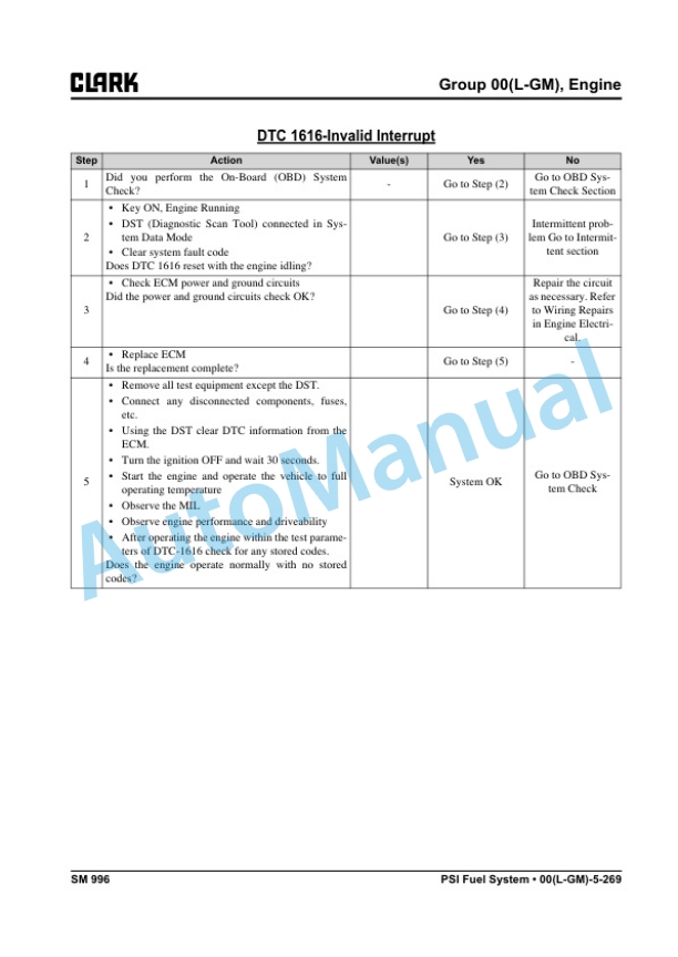
Clark C20, 25, 30, 35 D, L, G, C20, 25, 30, 32C L Service Manual SM-996
$30.00
Clark Service Manual PDF
Clark 5000 Series Powershift Transmission Maintenance and Service Manual SM-54
$30.00
Clark Service Manual PDF
Clark C 20, 25, 30, 35 L-G, C 20, 25, 30, 32C L Service Manual SM-1044
$30.00
- Claas
- Grove
- New Holland
- Komatsu
- Kubota
- John Deere
- Linde
- Bomag
- CASE
- Clark
- JCB
- Jungheinrich
- Linde
- Yale
- Yanmar
- Manitou
- Manitowoc
- CNH
- Doosan
- Fiatagri
- Fiatallis
- Fiatallis Other Manual PDF
- Flexi Coil
- Ford New Holland
- Ford New Holland Other Manual PDF
- Huyndai
- Hypac
- Hyster
- Hyster Service Manual PDF
- Isuzu
- Kobelco
- Kohler
- Krupp
- Lombardini
- Mahindra
- Nuvera
- Perkins
- Sperry New Holland
- Utilev
- Versatile
- ZF