- Claas
- Grove
- New Holland
- Komatsu
- Kubota
- John Deere
- Linde
- Bomag
- CASE
- Clark
- JCB
- Jungheinrich
- Linde
- Yale
- Yanmar
- Manitou
- Manitowoc
- CNH
- Doosan
- Fiatagri
- Fiatallis
- Fiatallis Other Manual PDF
- Flexi Coil
- Ford New Holland
- Ford New Holland Other Manual PDF
- Huyndai
- Hypac
- Hyster
- Hyster Service Manual PDF
- Isuzu
- Kobelco
- Kohler
- Krupp
- Lombardini
- Mahindra
- Nuvera
- Perkins
- Sperry New Holland
- Utilev
- Versatile
- ZF


Linde 1102-02 – ECR30, ECR40 Production site LMH-NA Workshop Manuals SN A11102V00001 and up
$50.00
- Type Of Manual: Workshop Manuals
- Manual ID: SN A11102V00001 and up
- Format: PDF
- Size: 47.2MB
- Number of Pages: 332
- Serial Number:
SN A11102V00001 and up
Category: Linde Workshop Manual PDF
-
Model List:
- ECR30
- ECR40
- 1. Service case Release tools for contacts
- 1.1. Table of content
- 1.2. Safety information
- 1.2.1. Safety information for repair and maintenance work
- 1.3. Information
- 1.3.1. Information
- 1.4. Overview
- 1.4.1. Overview of service cases
- 1.5. Plug systems
- 1.5.1. ATS 2.8 plug connector
- 1.5.2. CMC plug connector
- 1.5.3. DCS 9.5 plug connector
- 1.5.4. DIN 1.5mm circular connector
- 1.5.5. DIN 2.5mm circular connector
- 1.5.6. Deutsch DTM plug connector
- 1.5.7. ECU appliance plug
- 1.5.8. MCON appliance plug
- 1.5.9. Appliance plug with JPT and MQS contacts
- 1.5.10. Appliance plug with MT2 and JPT contacts
- 1.5.11. SICMA appliance plug
- 1.5.12. Econoseal JMark 2 plug connector
- 1.5.13. Elobau 11pin receptacle housing
- 1.5.14. E5931 plug connector
- 1.5.15. FASTINFASTON 6.3mm plug connector
- 1.5.16. GT150 plug connector
- 1.5.17. HDSCS plug connector
- 1.5.18. JPT plug connector
- 1.5.19. JPT SLD plug connector
- 1.5.20. JPT plug connector Saab
- 1.5.21. JPT plug connector VW
- 1.5.22. Kompakt 1.1 plug connector
- 1.5.23. Bosch Kompakt 4 plug connector
- 1.5.24. Leavyseal plug connector
- 1.5.25. MCON 1.2mm LL plug connector
- 1.5.26. MCON 1.2mm CB plug connector
- 1.5.27. MCP plug connector
- 1.5.28. MetriPack 150 plug connector
- 1.5.29. MiniFit plug connector
- 1.5.30. Mini Universal MATENLOK plug connector
- 1.5.31. Mini relay socket for DFK 1.3 and MDK 1.3
- 1.5.32. MKR Plus plug connector
- 1.5.33. MQS plug connector
- 1.5.34. MR plug connector
- 1.5.35. MTA plug housing and fuse housing
- 1.5.36. MT2 plug connector
- 1.5.37. MT2 1.5mm plug connector VW
- 1.5.38. Multilock plug connector
- 1.5.39. MX150 plug connector
- 1.5.40. NG1 plug connector
- 1.5.41. Phönix Contact HC plug connector
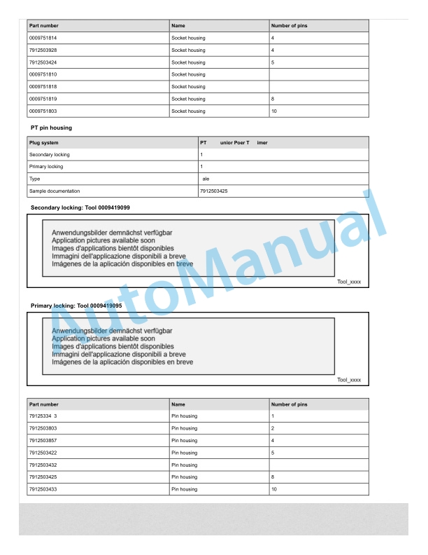
- 1.5.42. PT 3F plug connector
- 1.5.43. Relay socket with SPT contacts for DFK 1.3.4 and MDK 1.3.4
- 1.5.44. Relay socket with SPT and MPT contacts
- 1.5.45. Fuse holder with SPT contacts
- 1.5.46. Sicma plug connector
- 1.5.47. SLK 2.8 plug connector
- 1.5.48. Souriau UTL7 plug connector
- 1.5.49. Superseal 1.5mm plug connector
- 1.5.50. Trident Neptune plug connector
- 1.5.51. Universal MATENLOK plug connector
- 1.5.52. VW 9.5mm plug connector
- 2. Electric trucksECR30, ECR40
- 2.1. Table of content
- 2.2. Product information
- 2.2.1. Product Marking
- 2.2.1.1. Notes
- 2.2.1.2. Serial Number Location
- 2.2.1.3. Interpreting the Serial Number
- 2.2.1.4. Decal and Data Plate Location Manual Steer
- 2.2.1.5. Decal and Data Plate Location Electric Steer
- 2.2.2. Specifications
- 2.2.2.1. Specifications Manual Steer
- 2.2.2.2. Specifications Electric Steer
- 2.3. Maintenance
- 2.3.1. Routine Lubrication and Inspection
- 2.3.1.1. Routine Lubrication and Inspection Intervals
- 2.3.1.2. Minimum Lubrication and Inspection Intervals
- 2.3.1.3. Check Casters
- 2.3.1.4. Lubricate Load Wheel Axles
- 2.3.1.5. Check for Gear Oil Leakage
- 2.3.1.6. Check Lift Cylinder and Lines for Leaks
- 2.3.1.7. Check Hydraulic Oil Level
- 2.3.1.8. Check Drive Wheel and Fasteners
- 2.3.1.9. Lubricate Drive Axle Swivel Bearing
- 2.3.1.10. Lubricate Tie Bar Linkage
- 2.3.1.11. Lubricate Lift Cylinder and Fork Frame Pivots
- 2.3.1.12. Lubricate Caster Swivel Bearings
- 2.3.1.13. Lubricate Steering Gear (Electric steer only)
- 2.3.2. Scheduled Maintenance
- 2.3.2.1. General Maintenance Information
- 2.3.2.2. Maintenance Schedule
- 2.3.3. Fluids and Lubricants
- 2.3.3.1. Fluid and Lubricant Specifications
- 2.3.3.2. Capacities
- 2.4. Drive Motor and Brake
- 2.4.1. Drive Motor
- 2.4.1.1. Drive Motor Description
- 2.4.1.2. Testing
- 2.4.1.3. Drive Motor Replacement
- 2.4.1.4. Speed Sensor (B1)
- 2.4.1.5. Temperature Sensor (B4)
- 2.4.2. Brake
- 2.4.2.1. Brake Description
- 2.4.2.2. Manual Brake Release
- 2.4.2.3. Checking Brake Disc Clearance
- 2.4.2.4. Checking the Brake Coil
- 2.4.2.5. Brake Coil.Disc Replacement
- 2.5. Drive Unit
- 2.5.1. Transmission
- 2.5.1.1. Description
- 2.5.1.2. Transmission Removal and Installation
- 2.5.1.3. Components
- 2.5.2. Drive Wheel
- 2.5.2.1. Drive Wheel
- 2.6. Chassis
- 2.6.1. Fork Linkage
- 2.6.1.1. Chassis and Linkage
- 2.6.1.2. Fork Height Adjustment
- 2.6.2. Load Wheels and Shackles
- 2.6.2.1. Description
- 2.6.2.2. Shackle Replacement
- 2.6.2.3. Load Wheel Replacement
- 2.6.3. Floor Plate
- 2.6.3.1. Floor Plate
- 2.6.4. Casters
- 2.6.4.1. Caster Description
- 2.6.4.2. Caster Adjustment
- 2.7. Steering
- 2.7.1. Steering Variants
- 2.7.1.1. Steering Variants
- 2.7.2. Manual Steering
- 2.7.2.1. Manual Steer Connector Plate
- 2.7.2.2. Steering Bearing Replacement
- 2.7.3. Electric Steering (Optional Equipment)
- 2.7.3.1. Electric Steering System
- 2.7.3.2. Electric Steer Motor Unit (3A1)
- 2.7.3.3. Steer Motor Components
- 2.7.3.4. Steer Motor Contactor (3K1)
- 2.7.3.5. Steer Angle Control Unit (7A1)
- 2.7.3.6. Steer Angle Control Unit Replacement
- 2.7.3.7. Steer Brake Feature
- 2.7.3.8. Calibrating the Electric Steering System
- 2.7.3.9. Electric Steering System Fault Codes
- 2.8. Controls
- 2.8.1. Handle Manual Steer
- 2.8.1.1. Control Handle Removal and Installation
- 2.8.2. Control Head Manual Steer
- 2.8.2.1. Control Head Description
- 2.8.2.2. Throttle Mechanism
- 2.8.2.3. Horn Button
- 2.8.2.4. Brake Button
- 2.8.3. Control Head Electric Steer
- 2.8.3.1. Control Head Description
- 2.9. Electrical
- 2.9.1. Electrical System Overview
- 2.9.1.1. Electrical System Description
- 2.9.1.2. Fuses
- 2.9.1.3. Wiring and Connector Location
- 2.9.2. Switches
- 2.9.2.1. Key Switch (S1)
- 2.9.2.2. Floor Plate Switch (1S1)
- 2.9.2.3. Lift Limit Switch (2S1)
- 2.9.2.4. Auxiliary Lift and Lower Switches (option)
- 2.9.2.5. Order Pick Switches Electric steer variant (option)
- 2.9.3. Contactor
- 2.9.3.1. Contactor (K1)
- 2.9.4. Horn
- 2.9.4.1. Horn (H1)
- 2.9.6. Travel Alarm
- 2.9.6.1. Travel Alarm.Options Connector X9
- 2.9.7. Main Controller
- 2.9.7.1. Main Controller
- 2.9.7.2. Main Controller Connector 1X1
- 2.9.7.3. Main Controller Program
- 2.9.7.4. Adjustable Parameters
- 2.9.7.5. Main Controller Troubleshooting
- 2.9.7.6. Main Controller Replacement
- 2.9.7.7. Fault Codes
- 2.9.8. Control Head Manual Steer
- 2.9.8.1. Control Head Overview
- 2.9.8.2. Control Head Disassembly
- 2.9.8.3. Control Head Switches
- 2.9.8.4. Control Head Circuit Board Components (Throttle Potentiometer and Brake Switch)
- 2.9.9. Control Head Electric Steer
- 2.9.9.1. Control Head Overview
- 2.9.9.2. Control Module and Throttle
- 2.9.9.3. Control Module Removal
- 2.9.9.4. Control Module Disassembly
- 2.9.9.5. Calibrating the Throttle Potentiometer Electric Steer
- 2.9.9.6. CAN Converter Module (A5)
- 2.9.10. Display Unit (6P3)
- 2.9.10.1. Description
- 2.9.10.2. Operation
- 2.9.10.3. Service Timer
- 2.9.10.4. Battery Discharge Indication
- 2.10. Hydraulic
- 2.10.1. Hydraulic System Description
- 2.10.1.1. Hydraulic System
- 2.10.2. Lift Cylinder
- 2.10.2.1. Lift Cylinder
- 2.10.2.2. Lift Cylinder Replacement
- 2.10.2.3. Lift Cylinder Overhaul
- 2.10.3. Hydraulic Pump Unit
- 2.10.3.1. Hydraulic Pump Unit Components
- 2.10.3.2. Hydraulic Pump Unit
- 2.10.4. Hydraulic Pump Motor
- 2.10.4.1. Pump Motor (2M1)
- 2.10.4.2. Hydraulic Pump Motor Components
- 2.10.5. Hydraulic Pump
- 2.10.5.1. Hydraulic Pump
- 3. Circuit DiagramsECR30, ECR40
- 3.1. Table of content
- 3.2. Circuit diagrams
- 3.2.1. Wiring diagram
- 3.2.1.1. Electrical Schematic page 1 Power Circuit (Both steering variants)
- 3.2.1.2. Electrical Schematic page 2 Control Circuit Manual Steer
- 3.2.1.3. Electrical Schematic page 3 Control Circuit Electric Steer
- 3.2.2. Hydraulic circuit diagram
- 3.2.2.1. Hydraulic Diagram
Rate this product
You may also like


Linde Workshop Manual PDF
$50.00


Linde Workshop Manual PDF
Linde 1102-01 – ECR27, ECR36 Production site LMH-NA Workshop Manuals
$50.00


- Claas
- Grove
- New Holland
- Komatsu
- Kubota
- John Deere
- Linde
- Bomag
- CASE
- Clark
- JCB
- Jungheinrich
- Linde
- Yale
- Yanmar
- Manitou
- Manitowoc
- CNH
- Doosan
- Fiatagri
- Fiatallis
- Fiatallis Other Manual PDF
- Flexi Coil
- Ford New Holland
- Ford New Holland Other Manual PDF
- Huyndai
- Hypac
- Hyster
- Hyster Service Manual PDF
- Isuzu
- Kobelco
- Kohler
- Krupp
- Lombardini
- Mahindra
- Nuvera
- Perkins
- Sperry New Holland
- Utilev
- Versatile
- ZF