


Linde Operator Manual PDF
$20.00
Linde Operator Manual PDF
Linde 1110-01 – N20C, N20VI, N20VLI, V08-01, V08-02 Operating Instructions SN W41110V00529 and up
$20.00

Linde Operator Manual PDF
Linde 1102-01 – ECR27, ECR36 Production site LMH-NA Operating Instructions
$20.00

Linde Operator Manual PDF
Linde 1110-01 – V08-01, V08-02 Operating Instructions SN 11.09 and up SN up to W41110V00528
$20.00

Linde Operator Manual PDF
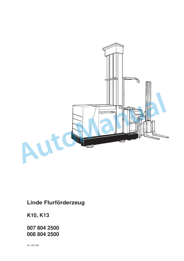
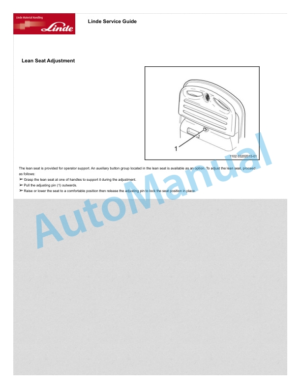
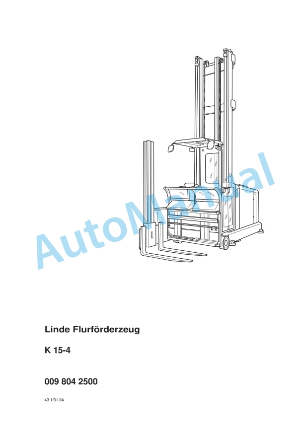
Linde 011-01 – K Generation 1 2, K Generation 3, K Generation 4 Operating Instructions
$20.00
Linde Operator Manual PDF
Linde 1120-01 – R-matic, R10, R12, R14, R16, R20, R25 Operating Instructions SN 10.12 and up
$20.00

