- Claas
- Grove
- New Holland
- Komatsu
- Kubota
- John Deere
- Linde
- Bomag
- CASE
- Clark
- JCB
- Jungheinrich
- Linde
- Yale
- Yanmar
- Manitou
- Manitowoc
- CNH
- Doosan
- Fiatagri
- Fiatallis
- Fiatallis Other Manual PDF
- Flexi Coil
- Ford New Holland
- Ford New Holland Other Manual PDF
- Huyndai
- Hypac
- Hyster
- Hyster Service Manual PDF
- Isuzu
- Kobelco
- Kohler
- Krupp
- Lombardini
- Mahindra
- Nuvera
- Perkins
- Sperry New Holland
- Utilev
- Versatile
- ZF
 Service Manual 1")
 Service Manual 2")
 Service Manual 3")
 Service Manual 4")
 Service Manual 5")
Hyster D114 (E25-40XM) Service Manual
$30.00
- Type Of Manual: Service Manual
- Number of Pages: 795
- Size: 40.0MB
- Format: PDF
Category: Hyster Service Manual PDF
-
Model List:
- D114 (E25-40XM)
- 1. INTRODUCTION
- 2. GENERAL
- 3. LEAD-ACID BATTERIES
- 4. SPECIFIC GRAVITY
- 5. THE CHEMICAL REACTION IN A CELL
- 6. ELECTRICAL TERMS
- 7. HOW TO SELECT THE BATTERY
- 8. VOLTAGE OF A BATTERY
- 9. THE BATTERY AS A COUNTERWEIGHT
- 10. BATTERY RATINGS
- 11. Kilowatt-Hours
- 12. BATTERY MAINTENANCE
- 13. SAFETY PROCEDURES
- 14. MAINTENACE RECORDS
- 15. THE NEW BATTERY
- 16. HOW TO CLEAN THE BATTERY
- 17. HOW TO ADD WATER
- 18. THE HYDROMETER
- 19. BATTERY TEMPERATURE
- 20. CHARGING THE BATTERY
- 21. Types Of Battery Charges
- 22. Methods Of Charging
- 23. Troubleshooting The Charger
- 24. How To Know When The Battery Is Fully Charged
- 25. WHERE TO CHARGE THE BATTERIES
- 26. Equipment Needed
- 27. BATTERY CONNECTORS
- 28. BATTERY CARE
- 29. INTRODUCTION
- 30. GENERAL
- 31. DESCRIPTION
- 32. Main Frame
- 33. Other Frame Weldments
- 34. Battery Restraint And Hood Frame
- 35. Overhead Guard
- 36. REPAIRS
- 37. OVERHEAD GUARD
- 38. Removal
- 39. Installation
- 40. BATTERY RESTRAINT AND SEAT ASSEMBLY
- 41. COUNTERWEIGHT
- 42. Removal
- 43. Installation
- 44. TRACTION MOTOR
- 45. Removing Traction Motor
- 46. Installing Traction Motor
- 47. HYRAULIC TANK
- 48. Inspection
- 49. Repairs, Small Leaks
- 50. Repairs, Large Leaks
- 51. Cleaning
- 52. Steam Method of Cleaning
- 53. Chemical Solution Method Of Cleaning
- 54. Additional Preparations For Repair
- 55. PAINTING INSTRUCITONS
- 56. LABEL REPLACEMENT
- 57. DC Motor Maintenance
- 58. Safety Precautions Maintenance and Repair
- 59. General
- 60. Brush and Commutator Inspection
- 61. Hydraulic Pump Motor and Traction Motor
- 62. Steering Pump Motor
- 63. Normal Commutator Surface
- 64. Commutator Problems
- 65. Brush Replacement
- 66. Stoning the Commutator
- 67. Motors Repair
- 68. Disassemble
- 69. Traction Motor and Hydraulic Pump Motor
- 70. Steering Pump Motor
- 71. Assemble
- 72. Traction Motor and Hydraulic Pump Motor
- 73. Steering Pump Motor
- 74. Brush Alignment, Traction and Hydraulic Motors
- 75. Tests for Damaged Field and Armature
- 76. Test for an Open Circuit in Armature
- 77. Test for Short Circuit in One Armature Winding
- 78. Test for Short Circuit to Armature Shaft
- 79. Test for Open Circuit in Field Coil
- 80. Test for Short Circuit in Field Coil
- 81. Test for Short Circuit between Field and Motor Case
- 82. Brush Holder Test
- 83. Troubleshooting
- 84. Table 1. Normal Commutator Surfaces
- 85. Table 2. Commutator Problems
- 86. Table 3. Brush Wear Replacement Guide
- 87.
- 87.1. INTRODUCTION
- 87.2. REPAIRS
- 87.3. TORQUE SPECIFICATIONS
- 87.4. TROUBLESHOOTING
- 88.
- 88.1. STEERING SYSTEM
- 88.2. POWER STEERING MOTOR AND PUMP
- 88.3. HYDRAULIC STEERING MOTOR
- 88.4. CHECKS AND ADJUSTMENTS
- 88.5. TROUBLESHOOTING
- 89.
- 89.1. INTRODUCTION
- 89.2. REPAIRS
- 89.3. CHECKS AND ADJUSTMENTS
- 89.4. TROUBLESHOOTING
- 90.
- 90.1. INTRODUCTION
- 90.2. REPAIRS
- 90.3. TORQUE SPECIFICATIONS
- 90.4. TROUBLESHOOTING
- 91.
- 91.1. INTRODUCTION
- 91.2. TORQUE SPECIFICATIONS
- 91.3. TROUBLESHOOTING
- 92.
- 92.1. INTRODUCTION
- 92.2. REPAIRS
- 92.3. CHECKS AND ADJUSTMENTS
- 92.4. TROUBLESHOOTING CHART
- 92.5. SPECIFICATIONS
- 93.
- 93.1. INTRODUCTION
- 93.2. REPAIRS
- 93.3. CHECKS AND ADJUSTMENTS
- 93.4. TROUBLESHOOTING
- 94.
- 95.
- 96.
- 96.1. Electrical System
- 96.2. Safety Precautions Maintenance and Repair
- 96.3. General
- 96.4. Description
- 96.5. ZX Series Display Panels
- 96.6. Display Panel
- 96.7. Basic Display Panels
- 96.8. Performance Display
- 96.9. Brush Wear Indicators
- 96.10. SEM Display Panels – Features
- 96.11. Descriptions of Common Features
- 96.12. Additional Features of Premium Display Panel
- 96.13. Descriptions of Additional Features
- 96.14. SEM Display Panel Indicators
- 96.15. All Indicator Symbols
- 96.16. Hourmeter Indicator Symbol
- 96.17. Wrench Indicator Symbol
- 96.18. Battery Indicator Symbol
- 96.19. Battery State-of-Charge (BDI)
- 96.20. Brake Fluid Too Low Symbol
- 96.21. Parking Brake Symbol
- 96.22. Fasten Seat Belt Symbol
- 96.23. LCD Screen (Standard Display Panel)
- 96.24. Additional Components of Premium Display Panel
- 96.25. Alpha Numerical Screen
- 96.26. STAR Push Button
- 96.27. Push Buttons 1 Through 5 – SEM
- 96.28. Other Control Components
- 96.29. Display Panel Components Replacement
- 96.30. ZX Panel Replacement
- 96.31. Display Panel Assembly
- 96.32. Key Switch, Replace
- 96.33. Indicator LEDs
- 96.34. Battery Indicators
- 96.35. Digital Display (Performance Display Panel Only)
- 96.36. Status Code or Performance Level Switches and Indicator LEDs (Pe
- 96.37. Basic Display Panel, Replace Parts
- 96.38. Performance Display Panel, Replace Parts
- 96.39. SEM Display Panel Replacement
- 96.40. Motor Controller (SR or SP) Replacement
- 96.41. Control Components Replacement
- 96.42. Start Switch, Replace
- 96.43. Brake Light Switch, Replace
- 96.44. Seat Switch, Replace
- 96.45. External Seat Switch, Adjust
- 96.46. Switch for Optional Seat Brake, Replace
- 96.47. Parking Brake Switch, Replace
- 96.48. Direction Switches (MONOTROL Pedal), Replace
- 96.49. Direction Control Switches (Steering Column), Replace
- 96.50. Direction Control Switches, E70-120XL 3 (Steering Column)
- 96.51. Brake Fluid Switch, Replace
- 96.52. Brush Wear and Overtemperature Sensors
- 96.53. Rocker Switches for Lights
- 96.54. Accelerator Position Sensor, Replace
- 96.55. On-Demand Steering Components
- 96.56. Lights, Converter, Relay, and Reverse Alarm
- 96.57. Brake, Tail, and Reverse Light Assembly, Replace
- 96.58. Flashing Light Assembly, Replace
- 96.59. Front, Rear Driving Light, or Spot Light Assemblies, Replace
- 96.60. Operator Compartment Light Assembly, Replace
- 96.61. Converter, Replace
- 96.62. Relay, Replace
- 96.63. Reverse Alarm, Replace
- 96.64. Horn and Horn Button
- 96.65. Horn Switch and Cover
- 96.66. Hydraulic Pump Switches
- 96.67. Control and Power Fuses Check
- 96.68. Brush Wear and Overtemperature Sensors Check – ZX
- 96.69. Thermal Sensors – SEM Check
- 96.70. Start Switch Adjustment
- 96.71. Accelerator Potentiometer and Start Switch E70-120XL, E70-120XL
- 96.72. E70-120XL
- 96.73. E70-120XL 3
- 96.74. Direction Switches (MONOTROL)
- 96.75. Brake Light Switch Adjustment
- 96.76. Seat Switch Check
- 96.77. Optional Seat Brake Switch Adjustment
- 96.78. Parking Brake Switch Adjustment
- 96.79. Direction Switches Check
- 96.80. Monotrol Pedal
- 96.81. Steering Column
- 96.82. Hydraulic Pump Switch Adjustment
- 96.83. MONOTROL or Accelerator Pedal Adjustment
- 96.84. Accelerator Position Sensor Adjustment
- 97.
- 98.
- 98.1. TROUBLESHOOTING AND ADJUSTMENTS WITH A COMPUTER For EV-100ZX, EV-T100, SR (SEM) And SP Motor Controllers
- 99.
- 99.1. EV-100ZX SCR MOTOR CONTROLLER, Parameter Tables
- 99.2. TABLE 1. EV-100ZX Parameters (Heavey Duty Motor (8702303) Traction Card Type ZH or Zy With Regenerative Braking
- 99.3. TABLE 2. EV-100ZX Parameters (Heavy Duty Motor (8702303) Traction Card Type ZH or ZY No Regenerative Braking
- 99.4. TABLE 3. EV-100ZX Parameters (Standard Motor (P/N 8702301 or 8702302) Traction Card Type ZH or ZY With Regen. Braking
- 99.5. TABLE 4. EV-100ZX Parameters (Standard Motor (P/N 8702301 or 8702302) Traction Card Type ZH or ZY No Regen. Braking
- 99.6. TABLE 5. EV-100ZX Parameters-(Standard Motor (P/N 8702301 or 8702302) (Low Energy System)(Traction Card Type ZH and ZY
- 99.7. TABLE 6. EV-100ZX Parameters (Standard System) (Hydraulic Pump Card Type ZP With or Without Lift Interrupt)
- 99.8. TABLE 7. EV-100ZX Parameters (Low Energy System) (Hydraulic Pump Card Type ZP With or Without Lift Interrupt)
- 100.
- 100.1. EV-T100 TRANSISTOR MOTOR CONTROLLER, Parameter Tables
- 101.
- 102.
- 103.
- 103.1. INTRODUCTION
- 104.
- 104.1. INTRODUCTION
- 104.2. SAFETY PROCEDURES WHEN WORKING NEAR THE MAST
- 104.3. REPAIRS
- 104.4. CHECKS AND ADJUSTMENTS
- 104.5. TROUBLESHOOTING
- 105.
- 106.
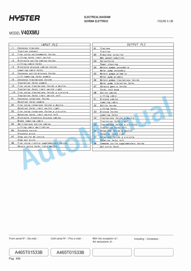
- 106.1. FIGURE 1. J2.00-3.200XM TRANSISTOR CONTROLLERS FOR TRACTION MOTOR AND HYDRAULIC PUMP MOTORS
- 106.2. FIGURE 2. E1.50-3.20XMS TRANSISTOR CONTROLLERS FOR TRACTION MOTOR AND HYDRAULIC PUMP MOTORS
- 106.3. FIGURE 3. SCHEMATIC DIAGRAM, TRANSISTOR CONTROLLERS FOR TRACTION MOTOR AND HYDRAULIC PUMP MOTORS
- 106.4. FIGURE 4. WIRING DIAGRAM, J2.00-3.20XM TRANSISTOR CONTROLLERS FOR TRACTION MOTOR AND HYDRAULIC PUMP MOTORS
- 106.5. FIGURE 5. WIRING DIAGRAM, J2.00-3.20XM TRANSISTOR CONTROLLER FOR TRACTION MOTOR, CONTACTOR CONTROLLER FOR HYDRAULIC PUMP
- 106.6. FIGURE 6. WIRING DIAGRAM, E1.50-3.20XMS TRANSISTOR CONTROLLERS FOR TRACTION MOTOR AND HYDRAULIC PUMP MOTORS
- 106.7. FIGURE 7. WIRING DIAGRAM, E1.50-3.20XMS TRANSISTOR CONTROLLER FOR TRACTION MOTOR, CONTACTOR CONTROL FOR HYDRAULIC PUMP
- 106.8. FIGURE 8. WIRE HARNESS, J2.00-3.20XM
- 106.9. FIGURE 9. POWER CABLES AND BATTERY CONNECTOR, J2.00-3.20XM
- 106.10. FIGURE 10. E1.50-3.20XM TRUCK WIRING
- 106.11. FIGURE 11. TRUCK POWER CABLES
- 106.12. FIGURE 12. TRUCK POWER CABLES
- 106.13. FIGURE 13. HYDRAULIC LINKAGE SWITCH AND CHASSIS WIRING DETAILS
- 106.14. FIGURE 14. WIRING SCHEMATIC FOR THE INSTRUMENT PANEL, E/J2.00-3.20XM
- 106.15. FIGURE 15. DISPLAY PANELS AND PLUG CONNECTIONS
- 106.16. FIGURE 16. CONFIGURATION OF THE EV-T100 MOTOR CONTROLLER MODULE
- 106.17. FIGURE 17. CONTROL CARD CONNECTIONS
- 106.18. FIGURE 18. TRUCK MANAGEMENT MODULE (TMM1)
- 106.19. FIGURE 19. WIRING SCHEMATIC, E2.00-3.20XM TRANSISTOR CONTROLLERS FOR TRACTION MOTOR AND HYDRAULIC PUMP MOTORS
- 106.20. FIGURE 20. DETAIL OF BATTERY CONNECTOR WITH 12 VOLT TAP
- 106.21. FIGURE 21. HYDRAULIC SCHEMATIC, E/J2.00-3.20XM E1.50-2.00XMS
- 106.22. FIGURE 22. WIRING DIAGRAM FOR LIGHTS
- 107.
- 107.1. WHEELS AND TIRES
- 107.2. COUNTERWEIGHTS
- 107.3. HYDRAULIC SYSTEM
- 107.4. CAPACITIES
- 107.5. BATTERY SPECIFICATIONS
- 107.6. BATTERY HEIGHT SPECIFICATIONS (Hoods and Battery Types)
- 107.7. MAXIMUM CARRIAGE AND TILT CREEP RATES
- 107.8. E25-40XM MAST SPEEDS (36 48 VOLT) Americas
- 107.9. E1.50-2.00XM MAST SPEEDS (48 VOLT) Europe
- 107.10. E25-40XM, E25-40XM2 MAST SPEEDS (3/99) Americas
- 107.11. E1.50-1.75XM E2.00XMS MAST SPEEDS (3/99) Europe
- 107.12. TORQUE SPECIFICATIONS
- 107.13. REFERENCE TABLE
- 108.
- 109.
- 109.1. INTRODUCTION
- 109.2. MAINTENANCE SCHEDULE
- 109.3. MAINTENANCE PROCEDURES
- 109.4. EVERY 8 HOURS OR DAILY
- 109.5. EVERY 350 HOURS OR TWO MONTHS
- 109.6. EVERY 2000 HOURS OR YEARLY
- 109.7. GENERAL PROCEDURES
- 109.8. REFERENCE TABLE
Rate this product
You may also like

Hyster Service Manual PDF
$30.00

Hyster Service Manual PDF
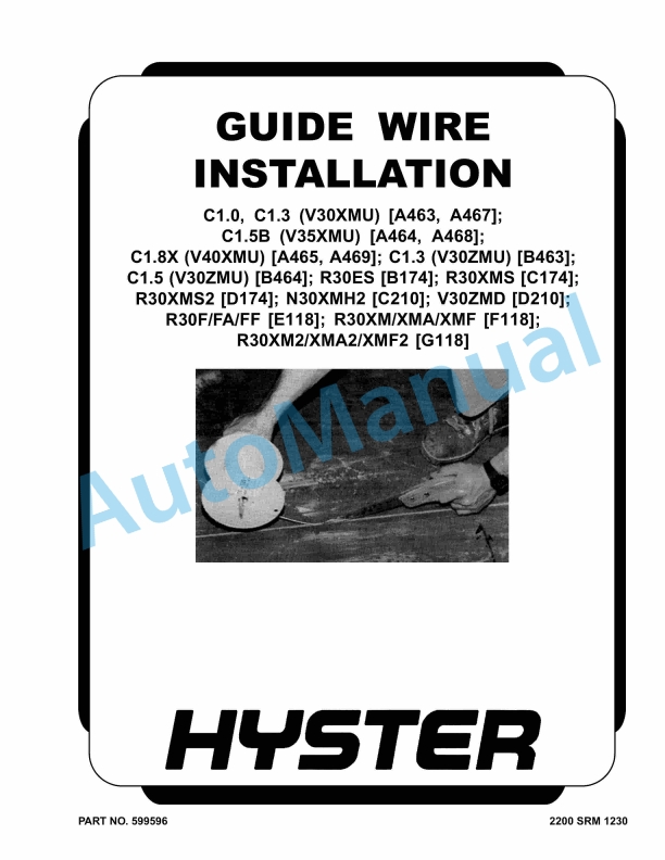
Hyster C1.0 to R30XMF2 Guide Wire Installation Maintenance And Repair
$30.00

%20Service%20Manual&url=https://automanual.net/doc/hyster-d114-e25-40xm-service-manual/&media=https://automanual.net/wp-content/uploads/2026/01/hyster-d114-e25-40xm-service-manual-1.jpg)
%20Service%20Manual&url=https://automanual.net/doc/hyster-c007-h150-275hp150-200b-service-manual/&media=https://automanual.net/wp-content/uploads/2026/01/hyster-c007-h150-275hp150-200b-service-manual-1.jpg)
%20Service%20Manual&url=https://automanual.net/doc/hyster-b174-r30es-service-manual/&media=https://automanual.net/wp-content/uploads/2026/01/hyster-b174-r30es-service-manual-1.jpg)
%20Service%20Manual&url=https://automanual.net/doc/hyster-c001-h1-25-1-75xl-service-manual/&media=https://automanual.net/wp-content/uploads/2026/01/hyster-c001-h125-175xl-service-manual-1.jpg)
%20Service%20Manual&url=https://automanual.net/doc/hyster-c002-s30-50c-service-manual/&media=https://automanual.net/wp-content/uploads/2026/01/hyster-c002-s30-50c-service-manual-1.jpg)
%20Service%20Manual&url=https://automanual.net/doc/hyster-a406-r1-4-r1-6-service-manual/&media=https://automanual.net/wp-content/uploads/2026/01/hyster-a406-r14-r16-service-manual-1.jpg)
%20Service%20Manual&url=https://automanual.net/doc/hyster-b210-n30ah-service-manual/&media=https://automanual.net/wp-content/uploads/2026/01/hyster-b210-n30ah-service-manual-1.jpg)
- Claas
- Grove
- New Holland
- Komatsu
- Kubota
- John Deere
- Linde
- Bomag
- CASE
- Clark
- JCB
- Jungheinrich
- Linde
- Yale
- Yanmar
- Manitou
- Manitowoc
- CNH
- Doosan
- Fiatagri
- Fiatallis
- Fiatallis Other Manual PDF
- Flexi Coil
- Ford New Holland
- Ford New Holland Other Manual PDF
- Huyndai
- Hypac
- Hyster
- Hyster Service Manual PDF
- Isuzu
- Kobelco
- Kohler
- Krupp
- Lombardini
- Mahindra
- Nuvera
- Perkins
- Sperry New Holland
- Utilev
- Versatile
- ZF