- Claas
- Grove
- New Holland
- Komatsu
- Kubota
- John Deere
- Linde
- Bomag
- CASE
- Clark
- JCB
- Jungheinrich
- Linde
- Yale
- Yanmar
- Manitou
- Manitowoc
- CNH
- Doosan
- Fiatagri
- Fiatallis
- Fiatallis Other Manual PDF
- Flexi Coil
- Ford New Holland
- Ford New Holland Other Manual PDF
- Huyndai
- Hypac
- Hyster
- Hyster Service Manual PDF
- Isuzu
- Kobelco
- Kohler
- Krupp
- Lombardini
- Mahindra
- Nuvera
- Perkins
- Sperry New Holland
- Utilev
- Versatile
- ZF
 Service Manual 1")
 Service Manual 2")
 Service Manual 3")
 Service Manual 4")
 Service Manual 5")
Hyster G160 (J1.60-2.00XMT) Service Manual
$30.00
- Type Of Manual: Service Manual
- Number of Pages: 863
- Size: 30.7MB
- Format: PDF
Category: Hyster Service Manual PDF
-
Model List:
- G160 (J1.60-2.00XMT)
- 1. RM0460-(08-1995)-UK-EN
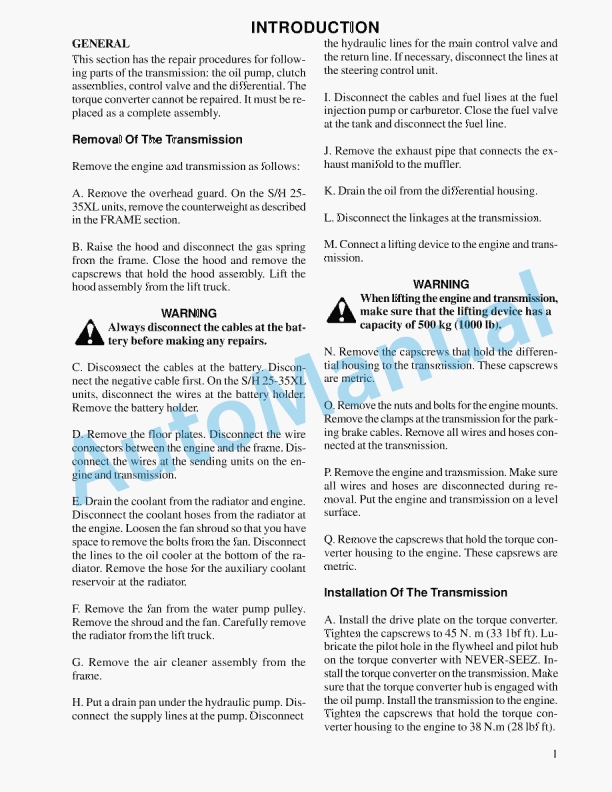
- 1.1. INTRODUCTION
- 1.2. DESCRIPTION
- 1.3. CHECKS AND ADJUSTMENTS
- 1.4. REPAIRS
- 1.5. TROUBLESHOOTING
- 2. RM0521-(03-2006)-UK-EN
- 2.1. Safety Precautions Maintenance and Repair
- 2.2. General
- 2.3. Description and Operation
- 2.4. Carriages
- 2.5. Mast Mounts
- 2.6. Two-Stage Mast, Limited Free-Lift (LFL)
- 2.7. Description and Operation
- 2.8. Two-Stage Mast, Full Free-Lift (FFL)
- 2.9. Description and Operation
- 2.10. Three-Stage Mast, Full Free-Lift (FFL)
- 2.11. Description and Operation
- 2.12. Four-Stage Mast
- 2.13. Description and Operation
- 2.14. Cylinder Cushion During Lifting Sequence
- 2.15. Cylinder Cushion During Lowering Sequence
- 3. RM0522-(07-2010)-UK-EN
- 3.1. Mast Repairs
- 3.2. Safety Precautions Maintenance and Repair
- 3.3. General
- 3.4. Safety Procedures When Working Near Mast
- 3.5. Fork Repair
- 3.6. Install
- 3.7. Carriages Repair
- 3.8. Standard Carriage, Remove
- 3.9. Hang-On Sideshift Carriage, Remove
- 3.10. Standard Carriage and Hang-On Sideshift Carriage, Repair
- 3.11. Standard Carriage, Install
- 3.12. Hang-On Sideshift Carriage, Install
- 3.13. Integral Sideshift Carriage
- 3.14. Clean and Inspect
- 3.15. Install
- 3.16. Mast Repair
- 3.17. Two-Stage LFL and Two-Stage FFL Masts, Disassemble
- 3.18. Three-Stage FFL Mast
- 3.19. Disassemble
- 3.20. Mast and Chains, Clean and Inspect
- 3.21. Two-Stage LFL and Two-Stage FFL Mast, Assemble
- 3.22. Three-Stage FFL Mast, Assemble
- 3.23. Install
- 3.24. Lift Cylinders Repair
- 3.25. Main Lift Cylinders, Remove
- 3.26. Free-Lift Cylinder, Remove
- 3.27. Cylinders, Disassemble
- 3.28. Two-Stage Full Free-Lift Mast, Right-Hand Main Lift Cylinder
- 3.29. Two-Stage Full Free-Lift Mast, Left-Hand Main Lift Cylinder
- 3.30. Two-Stage Limited Free-Lift Mast and Three-Stage Full Free-Lift
- 3.31. Two-Stage Limited Free-Lift Mast and Three-Stage Full Free-Lift
- 3.32. Two-Stage Full Free-Lift Mast and Three-Stage Full Free-Lift Mas
- 3.33. Clean and Inspect
- 3.34. Cylinders, Assemble
- 3.35. Two-Stage Full Free-Lift Mast, Right-Hand Main Lift Cylinder
- 3.36. Two-Stage Full Free-Lift Mast, Left-Hand Main Lift Cylinder
- 3.37. Two-Stage Limited Free-Lift Mast and Three-Stage Full Free-Lift
- 3.38. Two-Stage Limited Free-Lift Mast and Three-Stage Full Free-Lift
- 3.39. Two-Stage Full Free-Lift Mast and Three-Stage Full Free-Lift Mas
- 3.40. Main Lift Cylinders, Install
- 3.41. Free-Lift Cylinder, Install
- 3.42. Header Hose Arrangements
- 3.43. Two-Stage LFL Mast, New Hose Install
- 3.44. Two-Stage LFL Mast, Adjust Hoses After Installation
- 3.45. Two-Stage FFL Mast, New Hose Install
- 3.46. Two-Stage FFL Mast, Adjust Hoses After Installation
- 3.47. Three-Stage FFL Mast, New Hose Install
- 3.48. Three-Stage FFL Mast, Adjust Hoses After Installation
- 3.49. Header Hose Arrangement
- 3.50. Two-Stage LFL Mast, New Hose Install
- 3.51. Two-Stage LFL Mast, Adjust Hoses After Installation
- 3.52. Two-Stage FFL Mast, New Hose Install
- 3.53. Two-Stage FFL Mast, Adjust Hoses After Installation
- 3.54. Three-Stage FFL Mast, New Hose Install
- 3.55. Three-Stage FFL Mast, Adjust Hoses After Install
- 3.56. Lift and Tilt System Leak Check
- 3.57. Lift Cylinders Leak Check
- 3.58. Tilt Cylinders Leak Check
- 3.59. Tilt Cylinders Adjustment
- 3.60. Lift Chains Adjustment
- 3.61. Mast Adjustment
- 3.62. Carriage Adjustment
- 3.63. Troubleshooting
- 3.64. Table 1. Hook-Type Carriage Chain Adjustment
- 3.65. Table 2. Pin-Type Carriage Chain Adjustment
- 4. RM0568-(10-1999)-UK-EN
- 4.1. INTRODUCTION
- 4.2. REPAIRS
- 4.3. S2 SERIES TRANSAXLE
- 4.4. S1 SERIES TRANSAXLE
- 4.5. TROUBLESHOOTING
- 5. RM0570-(10-1999)-UK-EN
- 5.1. INTRODUCTION
- 5.2. REPAIRS
- 5.3. CHECKS AND ADJUSTMENTS
- 5.4. TROUBLESHOOTING
- 6. RM0576-(10-1999)-UK-EN
- 6.1. INTRODUCTION
- 6.2. REPAIRS
- 6.3. CHECKS AND ADJUSTMENTS
- 6.4. TROUBLESHOOTING
- 7. RM0586-(03-2002)-UK-EN
- 7.1. Capacities and Specifications
- 7.2. Safety Precautions Maintenance and Repair
- 7.3. Wheels and Tires
- 7.4. Motors (Dual Voltage 36/48)
- 7.5. Mast Tilt Performance
- 7.6. Mast Speeds
- 7.7. c Pump One- and Two-Speed Contactor
- 7.8. c Pump Transistor Control
- 7.9. c Pump One- and Two-Speed Contactor
- 7.10. c Pump Transistor Control
- 7.11. Mast/Tilt Drift Speeds
- 7.12. Hydraulic System
- 7.13. Torque Specifications
- 7.14. Transaxle
- 7.15. Brake System
- 7.16. Steering System
- 7.17. Hydraulic System
- 7.18. Mast/Tilt/Attachment Systems
- 7.19. Accelerator Potentiometer Checks
- 7.20. Adjustments
- 7.21. EV 100 LX Traction Card
- 7.22. EV 100 LX Pump Card
- 7.23. Controller Settings
- 7.24. SR/SP Traction Controller Settings – Standard With Auto Regen
- 7.25. SR/SP Traction Controller Settings – Standard Without Auto Decel
- 7.26. SR/SP Lift Pump Controller Settings
- 7.27. SR/SP Traction Controller Settings – 36V Energy Option
- 7.28. Battery Size Specifications
- 7.29. Type Lead Acid Battery
- 8. RM0588-(05-1995)-UK-EN
- 8.1. INTRODUCTION
- 8.2. REPAIRS
- 9. RM0655-(03-2002)-UK-EN
- 9.1. Steering Housing and Steering Control Unit
- 9.2. Safety Precautions Maintenance and Repair
- 9.3. General
- 9.4. Description
- 9.5. Operation
- 9.6. Steering Housing Repair
- 9.7. Remove and Disassemble
- 9.8. Assemble and Install
- 9.9. Steering Control Unit Repair
- 9.10. Disassemble
- 9.11. Assemble
- 9.12. Install
- 9.13. System Air Removal
- 9.14. Troubleshooting
- 10. RM0103-(03-2007)-UK-EN
- 10.1. Tilt Cylinders
- 10.2. Safety Precautions Maintenance and Repair
- 10.3. General
- 10.4. Description
- 10.5. Tilt Cylinder Repair
- 10.6. Disassemble
- 10.7. Assemble
- 10.8. Tilt Cylinders With O-Ring or Single-Lip Seals
- 10.9. Tilt Cylinders for XM and XMS Models
- 10.10. Tilt Cylinders for XL, XLS, and XL 3 Models
- 10.11. Tilt Cylinders for H700-800A and Early Model H700-920B
- 10.12. Install
- 10.13. Tilt Cylinders Using Chevron Packing
- 10.14. Tilt Cylinder Leak Check
- 10.15. Tilt Cylinder Stroke and Mast Tilt Angle Adjustment
- 10.16. Torque Specifications
- 10.17. Piston Rod Nut
- 10.18. Retainer
- 10.19. Troubleshooting
- 10.20. Table 1. Movement Rates (Maximum) for Tilt Cylinders
- 11. RM0231-(01-2016)-UK-EN
- 11.1. General
- 12. RM0687-(03-2002)-UK-EN
- 12.1. Steering System
- 12.2. Safety Precautions Maintenance and Repair
- 12.3. General
- 12.4. Operation
- 12.5. Steering Wheel and Column Assembly
- 12.6. Description
- 12.7. Install
- 12.8. Power Steering Pump and Motor
- 12.9. Description
- 12.10. Install
- 12.11. Disassemble
- 12.12. Assemble
- 12.13. Steering Axle Components
- 12.14. General
- 12.15. Wheel and Tire Assembly
- 12.16. Install
- 12.17. Wheel Hub Assembly
- 12.18. Install
- 12.19. Steering Axle Assembly
- 12.20. Install
- 12.21. Steering System Air Removal
- 12.22. Operation Check
- 12.23. Steering Pressure Check
- 12.24. Troubleshooting
- 13. RM0696-(03-2002)-UK-EN
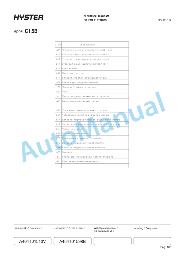
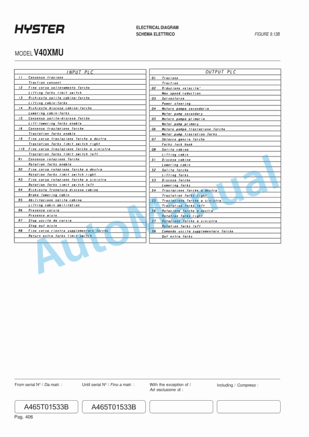
- 13.1. Diagrams
- 13.2. Safety Precautions Maintenance and Repair
- 14. RM0697-(08-2005)-UK-EN
- 14.1. SX/SR Transistor Motor Controllers and Handset
- 14.2. Safety Precautions Maintenance and Repair
- 14.3. Introduction to SEM
- 14.4. Advantages of Transistorized SEM
- 14.5. Features of SEM
- 14.6. Solid-State Reversing
- 14.7. Performance and Efficiency
- 14.8. Field Weakening
- 14.9. Regenerative Braking
- 14.10. SX Transistor Motor Controllers
- 14.11. Introduction
- 14.12. Proportional Operation for Dual-Motor Trucks
- 14.13. General
- 14.14. Operation
- 14.15. Controller Features
- 14.16. General
- 14.17. Creep Speed
- 14.18. Controlled Acceleration
- 14.19. Current Limit
- 14.20. Braking
- 14.21. Regenerative Braking to Zero Speed
- 14.22. Pedal Position Braking
- 14.23. Auto Braking
- 14.24. Conventional Plug Braking
- 14.25. Auxiliary Speed Control
- 14.26. Field Weakening
- 14.27. Speed Limits
- 14.28. Ramp Operation
- 14.29. Ramp Start
- 14.30. Antirollback
- 14.31. Steer Pump Contactor Time Delay
- 14.32. On-Board Coil Drivers and Internal Coil Suppression
- 14.33. System Protective Override
- 14.34. SRO (Static Return to Off)
- 14.35. Accelerator Volts Hold Off
- 14.36. Pulse Monitor Trip (PMT)
- 14.37. Thermal Protector (TP)
- 14.38. Low Voltage
- 14.39. SR Lift Pump Controllers
- 14.40. Sensor Interface/Contactor Driver Module
- 14.41. Diagnostic Status Codes and Troubleshooting
- 14.42. General Maintenance Instructions
- 14.43. Special Precautions
- 14.44. Diagnostics
- 14.45. Systems Diagnostics
- 14.46. Status Codes
- 14.47. Standard Status Codes
- 14.48. Stored Status Codes
- 14.49. Other Features
- 14.50. Hourmeter Readings
- 14.51. Maintenance Alert and Speed Limit
- 14.52. Battery Discharge Indication (BDI)
- 14.53. Internal Resistance Compensation
- 14.54. Handset Programmable
- 14.55. RS 232 Communication Ports
- 14.56. Circuit Board Coil Driver Modules
- 14.57. Maintenance Management Capability
- 14.58. Interactive Instrument Panel Modes
- 14.59. General Troubleshooting Instructions
- 14.60. Status Code Troubleshooting Tables
- 14.61. SX/SR Handset Instructions
- 14.62. General Features
- 14.63. Connecting the Handset
- 14.64. Startup Sequence
- 14.65. Setup Mode
- 14.66. Stored Status Code Mode
- 14.67. Clearing the Stored Status Codes
- 14.68. Restarting Lift Truck
- 14.69. SX Traction Controller Function Descriptions
- 14.70. Premium Instrument Panel Interactive Modes
- 14.71. SR Pump Controller Function Descriptions
- 14.72. Premium Instrument Panel Interactive Modes
- 14.73. Table 1. SX Traction Controller Connections/Descriptions
- 14.74. Table 2. SR Lift Pump Controller Connections/Descriptions/Status
- 14.75. Table 3. Instrument Panel Function Number Correlation
- 14.76. Table 4. Traction Function Settings Logic
- 14.77. Table 5. Lift Pump Function Settings Logic
- 14.78. Table 6. Speed/Torque Compensation
- 14.79. Table 7. Traction Controller Settings – Standard With Auto Regen
- 14.80. Table 8. Traction Controller Settings – Standard Without Auto Re
- 14.81. Table 9. Traction Controller Settings – High Performance With Au
- 14.82. Table 10. Lift Pump Controller Settings
- 15. RM0698-(03-2002)-UK-EN
- 15.1. Electrical System
- 15.2. Safety Precautions Maintenance and Repair
- 15.3. General
- 15.4. Electrical Compartment
- 15.5. Instrument Panels
- 15.6. Standard Display (Previous Configuration)
- 15.7. Standard Display (Current Configuration)
- 15.8. Premium Display (Previous Configuration)
- 15.9. Replacement (Previous Configuration)
- 15.10. Premium Display (Current Configuration)
- 15.11. Replacement (Current Configuration)
- 15.12. Control and Power Fuses
- 15.13. Steer Angle Potentiometer
- 15.14. General
- 15.15. Operation
- 15.16. Example
- 15.17. Installation
- 15.18. Positioning Steer Tire for Straight Travel
- 15.19. Adjustment
- 15.20. Handset Method
- 15.21. Voltmeter Method
- 15.22. Testing
- 15.23. Power Steering Control Assembly
- 15.24. General
- 15.25. Operation
- 15.26. Testing
- 15.27. Removal and Replacement
- 15.28. Power Steering Control Assembly
- 15.29. Optical Encoder
- 15.30. Lift Pump Control Board
- 15.31. General
- 15.32. Testing
- 15.33. Bypassing Lift Pump Control Board
- 15.34. Sensor Interface/Contactor Driver Module
- 15.35. General
- 15.36. Troubleshooting
- 15.37. Other Control Components
- 15.38. Key Switch
- 15.39. Seat Switch
- 15.40. Replace
- 15.41. Parking Brake Switch
- 15.42. Replace
- 15.43. Accelerator Switch Assembly
- 15.44. Replace
- 15.45. Direction Switches (MONOTROL Pedal)
- 15.46. Replace
- 15.47. Direction Switches (Steering Column)
- 15.48. Replace
- 15.49. Brake Fluid Switch
- 15.50. Hydraulic Cutoff Switch
- 15.51. Replace
- 15.52. Stop Light Switch
- 15.53. Replace
- 15.54. Motor Temperature Switches
- 15.55. Rocker Switches for Lights
- 15.56. DC to DC Converter
- 15.57. Backup Light Relay Panel
- 15.58. Backup Light Switch Relay
- 15.59. Horn and Horn Button
- 15.60. Horn Switch and Cover (Button)
- 15.61. Lights and Reverse Alarm
- 15.62. Light Assemblies Replacement
- 15.63. Tail Light
- 15.64. Flashing Light Assembly
- 15.65. Front Driving Light and Rear Work Light Assemblies
- 15.66. Spot Light Assembly
- 15.67. Table 1. Potentiometer Specifications
- 15.68. Table 2. Power Steering Control Assembly Specifications
- 15.69. Table 3. Lift Pump Control Board Test Point/Function Relationshi
- 15.70. Table 4. Lift Pump Control Board Troubleshooting Guide
- 15.71. Table 5. Lift Pump Control Board Test Values
- 15.72. Table 6. Lift Pump Control Board Bypass Test
- 15.73. Table 7. SICDM Connections/Descriptions/Status Codes
- 16. RM0699-(10-2007)-UK-EN
Rate this product
You may also like


Hyster Service Manual PDF
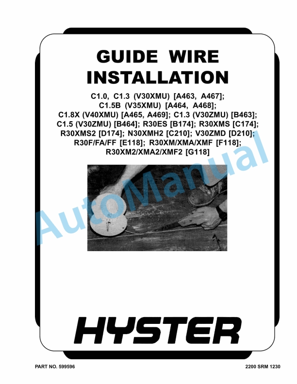
Hyster C1.0 to R30XMF2 Guide Wire Installation Maintenance And Repair
$30.00

%20Service%20Manual&url=https://automanual.net/doc/hyster-g160-j1-60-2-00xmt-service-manual/&media=https://automanual.net/wp-content/uploads/2026/01/hyster-g160-j160-200xmt-service-manual-1.jpg)
%20Service%20Manual&url=https://automanual.net/doc/hyster-b160-j25-35bs-service-manual/&media=https://automanual.net/wp-content/uploads/2026/01/hyster-b160-j25-35bs-service-manual-1.jpg)
%20Service%20Manual&url=https://automanual.net/doc/hyster-c098-e3-50-5-50xl-service-manual/&media=https://automanual.net/wp-content/uploads/2026/01/hyster-c098-e350-550xl-service-manual-1.jpg)
%20Service%20Manual&url=https://automanual.net/doc/hyster-c001-h25-35xl-service-manual/&media=https://automanual.net/wp-content/uploads/2026/01/hyster-c001-h25-35xl-service-manual-1.jpg)
%20Service%20Manual&url=https://automanual.net/doc/hyster-b168-j40-60xl-service-manual/&media=https://automanual.net/wp-content/uploads/2026/01/hyster-b168-j40-60xl-service-manual-1.jpg)
%20Maintenance%20Schedule&url=https://automanual.net/doc/hyster-c098-e3-50-5-50xl-e4-50xls-maintenance-schedule/&media=https://automanual.net/wp-content/uploads/2026/01/hyster-c098-e350-550xl-e450xls-maintenance-schedule-1.jpg)
Hyster Service Manual PDF
$30.00
- Claas
- Grove
- New Holland
- Komatsu
- Kubota
- John Deere
- Linde
- Bomag
- CASE
- Clark
- JCB
- Jungheinrich
- Linde
- Yale
- Yanmar
- Manitou
- Manitowoc
- CNH
- Doosan
- Fiatagri
- Fiatallis
- Fiatallis Other Manual PDF
- Flexi Coil
- Ford New Holland
- Ford New Holland Other Manual PDF
- Huyndai
- Hypac
- Hyster
- Hyster Service Manual PDF
- Isuzu
- Kobelco
- Kohler
- Krupp
- Lombardini
- Mahindra
- Nuvera
- Perkins
- Sperry New Holland
- Utilev
- Versatile
- ZF