- Claas
- Grove
- New Holland
- Komatsu
- Kubota
- John Deere
- Linde
- Bomag
- CASE
- Clark
- JCB
- Jungheinrich
- Linde
- Yale
- Yanmar
- Manitou
- Manitowoc
- CNH
- Doosan
- Fiatagri
- Fiatallis
- Fiatallis Other Manual PDF
- Flexi Coil
- Ford New Holland
- Ford New Holland Other Manual PDF
- Huyndai
- Hypac
- Hyster
- Hyster Service Manual PDF
- Isuzu
- Kobelco
- Kohler
- Krupp
- Lombardini
- Mahindra
- Nuvera
- Perkins
- Sperry New Holland
- Utilev
- Versatile
- ZF


Hyster H14.00-20.00XM to H20XMS-9 Steering Axle Maintenance And Repair
$30.00
- Type Of Manual: Maintenance And Repair
- Number of Pages: 1336
- Size: 90.9MB
- Format: PDF
Category: Hyster Service Manual PDF
-
Model List:
- H14.00-20.00XM, H16.00-18.00XM-12EC, H16.00-22.00XM-12EC, H16XM-12EC, H18XM-12EC, H22XM-12EC, H18XM-12EC, H22XM-12EC, H23XM-12EC, H16.00-18.00XM, H16.00-18.00XMS-12, H16XM-12, H18XM-12, H20XM-12, H22XM-12, H18XM-9, H18XMS-9, H20XM-9, H20XMS-9
- 1. RM0658-(09-2014)-US-EN
- 2. RM0661-(10-2014)-US-EN
- 3. RM0046-(11-2014)-US-EN
- 4. RM0135-(10-2011)-US-EN
- 4.1. Lift Cylinders
- 4.2. Safety Precautions Maintenance and Repair
- 4.3. Safety Procedures When Working Near Mast
- 4.4. General
- 4.5. Description
- 4.6. Lowering Control Valve
- 4.7. Cylinders (General)
- 4.8. Cylinders (H520-620B, H700-800A)
- 4.9. Retainer, Install
- 4.10. Cylinders (H360-460B)
- 4.11. Cylinders (Two-Speed)
- 4.12. Lift Cylinder Repair
- 4.13. Lift Cylinder Removal Without Removing Mast
- 4.14. Standard Masts With Main Lift Cylinder Fastened to Crossmember o
- 4.15. Standard and Full Free-Lift Masts With Lift Cylinder Fastened to
- 4.16. Masts That Have Two Cylinders, Main Lift Cylinder and Free-Lift
- 4.17. Disassemble
- 4.18. Assemble
- 4.19. Lift Cylinder Installation in Mast
- 4.20. Standard Masts With Main Lift Cylinder Fastened to Crossmember o
- 4.21. Standard and Full Free-Lift Masts With Lift Cylinder Fastened to
- 4.22. Chevron-Style Packing
- 4.23. Chevron-Style Packing Installation on Piston
- 4.24. Chevron-Style Packing Installation in Packing Gland
- 4.25. Lift Cylinders for VISTA Masts
- 4.26. Description
- 4.27. Lowering Control Valve
- 4.28. Disassemble
- 4.29. Assemble
- 4.30. Install
- 4.31. Main Lift Cylinders
- 4.32. Free-Lift Cylinder
- 4.33. Lift System Leak Check
- 4.34. Specifications
- 4.35. Troubleshooting
- 4.36. Table 1. Lift Trucks With Two-Speed Lift Cylinders
- 4.37. Table 2. Cylinder Retainer Torque Specifications and Weight Guid
- 5. RM0231-(01-2016)-US-EN
- 5.1. General
- 6. RM0951-(08-2014)-US-EN
- 7. RM1036-(01-2012)-US-EN
- 7.1. Brake Accumulator
- 7.2. Safety Precautions Maintenance and Repair
- 7.3. General
- 7.4. Description and Operation
- 7.5. Accumulator Maintenance
- 7.6. Pre-Charge Check
- 7.7. Pre-Charge Filling
- 7.8. Disassemble
- 7.9. Inspect
- 7.10. Assemble
- 7.11. Replace
- 7.12. Table 1. Accumulator Pressures
- 8. RM1101-(12-2015)-US-EN
- 8.1. Series Code / Model Designation Reference Table
- 8.2. General
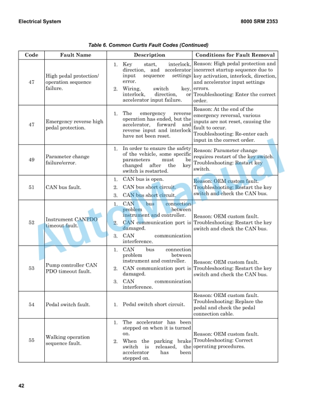
- 8.3. Fault Codes
- 9. RM1117-(01-2012)-US-EN
- 9.1. Parking Brake
- 9.2. Safety Precautions Maintenance and Repair
- 9.3. General
- 9.4. Description and Operation
- 9.5. Parking Brake Valve Replacement
- 9.6. Clean and Inspect
- 9.7. Install
- 9.8. Parking Brake Caliper Repair
- 9.9. Disassemble
- 9.10. Inspect
- 9.11. Install
- 9.12. Bleed Brakes
- 9.13. Brake Pad Repair
- 9.14. Inspect
- 9.15. Install
- 9.16. Seals Repair
- 9.17. Install
- 9.18. Specifications
- 9.19. Torque Requirements
- 9.20. Wear Limits
- 9.21. Lining to Disc Clearance
- 9.22. Troubleshooting
- 9.23. Table 1. Brake Pad Adjustment
- 9.24. Table 2. Torque Requirements
- 9.25. Table 3. Wear Limits
- 9.26. Table 4. Lining to Disc Clearance
- 10. RM1267-(03-2011)-US-EN
- 10.1. Safety Precautions Maintenance and Repair
- 10.2. General
- 10.3. Description
- 10.4. Counterweight Repair
- 10.5. General
- 10.6. Install
- 10.7. Air Cleaner Repair
- 10.8. Install
- 10.9. Hoods and Covers
- 10.10. Install
- 10.11. Floor Plates, Handrails, and Steps
- 10.12. Hydraulic Tank Repair
- 10.13. Small Leaks
- 10.14. Large Leaks
- 10.15. Steam Method
- 10.16. Chemical Solution Method
- 10.17. Other Methods of Preparation for Repair
- 10.18. Install
- 10.19. Fuel Tank Repair
- 10.20. Install
- 10.21. Exhaust System Repair
- 10.22. Install
- 10.23. Cab Repair
- 10.24. Rear Cab Assembly
- 10.25. Bottom Cab Assembly
- 10.26. Raising and Lowering Cab
- 10.27. Raise Cab
- 10.28. Lower Cab
- 10.29. Cab Repair
- 10.30. Install
- 10.31. Engine Repair
- 10.32. Install
- 10.33. Label Replacement
- 10.34. Table 1. Counterweight Weights
- 11. RM1270-(10-2014)-US-EN
- 12. RM1271-(03-2011)-US-EN
- 12.1. Transmission 0peration and Diagnostics
- 12.2. Safety Precautions Maintenance and Repair
- 12.3. General
- 12.4. Description
- 12.5. General
- 12.6. Operation
- 12.7. Hydraulic Operation
- 12.8. Variable Force Solenoids
- 12.9. Speed Engagement
- 12.10. Cooling and Lubrication
- 12.11. Control System
- 12.12. General
- 12.13. APC200 Controller
- 12.14. Self Test
- 12.15. Protection Modes
- 12.16. Fault Codes
- 12.17. Fault Log Mode
- 12.18. Fault Identification
- 12.19. Transmission Control Valve
- 12.20. Transmission Control Valve Repair
- 12.21. Pressure Check
- 12.22. Pressure Specifications
- 12.23. Pressure, Speed, and Temperature Sensors
- 12.24. Pressure Switch
- 12.25. Speed Sensor
- 12.26. Temperature Sensors
- 12.27. Dana Dashboard Software
- 12.28. Description
- 12.29. Connection
- 12.30. Transmission Test and Calibration
- 12.31. Precautions
- 12.32. Stall Test
- 12.33. Description
- 12.34. Stall Test Procedure
- 12.35. Clutch Filling Calibration
- 12.36. Description
- 12.37. Procedure
- 12.38. Inching Calibration
- 12.39. Description
- 12.40. Brake and Inching Pedal Adjustment
- 12.41. Inching Pedal Sensor Adjustment
- 12.42. Inching Pedal Sensor Calibration
- 12.43. APC200 Display Information
- 12.44. General
- 12.45. General Information Group
- 12.46. Fault Codes
- 12.47. Indication of Protection Modes
- 12.48. Test Function Group
- 12.49. Digital Input Test
- 12.50. Analog Input Test
- 12.51. Speed Sensor Test
- 12.52. Output Test
- 12.53. Voltage Test
- 12.54. Calibration Group
- 12.55. Calibration Mode
- 12.56. Clutch Filling Calibration
- 12.57. Heat Up Mode
- 12.58. Inching Pedal Sensor Calibration
- 12.59. Electrical Specifications
- 12.60. Table 1. Activated Solenoids and Gear Selection
- 12.61. Table 2. Pressure Specifications
- 12.62. Table 3. Transmission Housing Check Ports
- 12.63. Table 4. Sensors and Switches
- 12.64. Table 5. Speed Sensor Test Values
- 12.65. Table 6. General Information Group
- 12.66. Table 7. General Information Group
- 12.67. Table 8. Digital Input Test
- 12.68. Table 9. Analog Input Test
- 12.69. Table 10. Speed Sensor Test
- 12.70. Table 11. Output Test
- 12.71. Table 12. Voltage Test
- 12.72. Table 13. APC200 Wire Number to Hyster Wire Number Conversion
- 12.73. Table 14. Temperature Sensor (In Speed Sensor) Resistance Versus
- 13. RM1272-(03-2011)-US-EN
- 13.1. Steering System
- 13.2. Safety Precautions Maintenance and Repair
- 13.3. General
- 13.4. Description
- 13.5. Steering Wheel and Column Assembly Repair
- 13.6. General
- 13.7. Steering Wheel and Horn
- 13.8. Install
- 13.9. Steering Column
- 13.10. Install
- 13.11. Steering Control Unit Repair
- 13.12. General
- 13.13. Description
- 13.14. Operation
- 13.15. Disassemble
- 13.16. Assemble
- 13.17. Install
- 13.18. Steering System Air Removal
- 13.19. Troubleshooting
- 14. RM1275-(03-2011)-US-EN
- 14.1. Hydraulic System
- 14.2. Safety Precautions Maintenance and Repair
- 14.3. General
- 14.4. Description and Operation
- 14.5. Hydraulic Plate
- 14.6. Hydraulic Pumps
- 14.7. Steering Control System
- 14.8. Brake System
- 14.9. Tilt Control Valve
- 14.10. Hydraulic Pump Repair
- 14.11. General
- 14.12. Disassemble
- 14.13. Clean and Inspect
- 14.14. Assemble
- 14.15. Install
- 14.16. Pump Output Check
- 14.17. First Method
- 14.18. Second Method
- 14.19. Lift and Lower Circuit
- 14.20. Description
- 14.21. Operation
- 14.22. Lift Circuit
- 14.23. Lowering
- 14.24. Lowering Control Valves
- 14.25. Repairs
- 14.26. General
- 14.27. Remote Control Valve
- 14.28. Tilt Circuit
- 14.29. Description
- 14.30. Operation
- 14.31. Tilt Spool
- 14.32. Relief Valves in Main Control Valve
- 14.33. Tilt Control Valves
- 14.34. Repairs
- 14.35. General
- 14.36. Valves, Tilt Control Valves
- 14.37. Attachment Circuit Valves
- 14.38. Description and Operation
- 14.39. Other Hydraulic Components
- 14.40. Description and Operation
- 14.41. Relief Valves in Steering System
- 14.42. Hydraulic Filters
- 14.43. Hydraulic Filters
- 14.44. High Pressure Filter
- 14.45. Brake Filter
- 14.46. Return Line Filter
- 14.47. Hydraulic Tank Breather
- 14.48. Hydraulic Hose Repair
- 14.49. Checks and Adjustments
- 14.50. Main Function Relief Valve Pressure, Check
- 14.51. Oil Level, Check
- 14.52. Specifications
- 14.53. Hydraulic Pumps Output at 2200 rpm (Governed Speed)
- 14.54. Cummins 142Hp (190 kW)/164 Hp (220 kW) Engine
- 14.55. Relief Valves (Approximate Operating Pressures)
- 14.56. Check Port Pressures
- 14.57. Main Hydraulic Filters
- 14.58. Tank Capacity
- 14.59. Torque Specifications
- 14.60. Tilt Control Valve
- 14.61. Hydraulic Filters
- 14.62. Remote Control Valves
- 14.63. Troubleshooting
- 14.64. Lift and Lower Circuit
- 14.65. Tilt Circuit
- 14.66. Attachment Circuit Valves
- 14.67. Attachment Control Valve
- 14.68. Carriage Solenoid Valve
- 14.69. Other Hydraulic Components
- 14.70. Accumulator Circuit
- 14.71. Pilot Circuit
- 14.72. Park Brake Circuit
- 14.73. Table 1. Brake Treadle Settings
- 14.74. Table 2. Gauge Ranges
- 14.75. Table 3. Pressure Settings
- 15. RM1276-(03-2011)-US-EN
- 15.1. Tilt Cylinders
- 15.2. Safety Precautions Maintenance and Repair
- 15.3. General
- 15.4. Description
- 15.5. Tilt Cylinder Repair
- 15.6. Disassemble
- 15.7. Inspect
- 15.8. Assemble
- 15.9. Install
- 15.10. Tilt Cylinder Leak Check
- 15.11. Tilt Cylinder Stroke and Mast Tilt Angle Adjustment
- 15.12. Torque Specifications
- 15.13. Troubleshooting
- 15.14. Table 1. Movement Rate (Maximum) for Tilt Cylinders
- 16. RM1277-(03-2011)-US-EN
- 16.1. Hydraulic Plate
- 16.2. Safety Precautions Maintenance and Repair
- 16.3. General
- 16.4. Description and Operation
- 16.5. Hydraulic Oil Supply
- 16.6. Main Control Valve, Section 1 of Hydraulic Plate
- 16.7. Description
- 16.8. Operation
- 16.9. Combination Manifold, Section 2 of Hydraulic Plate
- 16.10. Main Control Valve, Section 1 of Hydraulic Plate
- 16.11. Disassemble
- 16.12. Lift Section
- 16.13. Tilt Section
- 16.14. Auxiliary Section
- 16.15. Relief Valve
- 16.16. Clean and Inspect
- 16.17. Assemble
- 16.18. Relief Valve
- 16.19. Auxiliary Section
- 16.20. Tilt Section
- 16.21. Lift Section
- 16.22. Install
- 16.23. Combination Manifold, Section 2 of Hydraulic Plate
- 16.24. General
- 16.25. Valves and Pressure Switches
- 16.26. Hydraulic Hose Repair
- 16.27. Hydraulic Hose Identification
- 16.28. Torque Values
- 16.29. Measurements and Adjustments
- 16.30. Measurements
- 16.31. Adjustments
- 16.32. Troubleshooting
- 16.33. Table 1. Pilot Hoses
- 16.34. Table 2. Brake Hoses
- 16.35. Table 3. Steer Hoses
- 16.36. Table 4. Pressure Settings at 2100 RPM
- 17. RM1282-(04-2015)-US-EN
- 18. RM1296-(08-2014)-US-EN
- 19. RM1297-(03-2011)-US-EN
- 19.1. Capacities and Specifications
- 19.2. Safety Precautions Maintenance and Repair
- 19.3. Counterweight Weights
- 19.4. Vehicle Weights
- 19.5. Container Attachment Weights
- 19.6. Capacities
- 19.7. Electrical System
- 19.8. Engine Specifications
- 19.9. Function Speeds
- 19.10. Steering
- 19.11. Tire Sizes
- 19.12. Hydraulic System Specifications
- 19.13. Torque Specifications
- 19.14. Main Control Valve
- 19.15. Electrical System
- 19.16. Alternator
- 19.17. Counterweight
- 19.18. Drive Axle
- 19.19. Planetary Gear Axle
- 19.20. Steering Axle
- 19.21. Wheel Bearing Adjusting Nut (PRC1756-W3H)
- 19.22. Differential
- 19.23. Transmission
- 19.24. Torque Converter
- 19.25. Steering
- 19.26. Wheel Nuts
- 19.27. Attachment
- 20. RM1390-(01-2016)-US-EN
- 20.1. Series Code / Model Designation Reference Table
- 20.2. General
- 20.3. Description of Operation
- 20.4. Remove and Install
- 20.5. Checks and Adjustments
- 21. RM1435-(01-2016)-US-EN
- 21.1. Series Code / Model Designation Reference Table
- 21.2. General
- 21.3. APC200 Fault Codes
- 22. RM1459-(12-2015)-US-EN
- 22.1. Series Code / Model Designation Reference Table
- 22.2. Description and Operation
- 22.3. Remove and Replace
- 23. RM1444-(03-2011)-US-EN
- 23.1. Transmission Repair
- 23.2. Safety Precautions Maintenance and Repair
- 23.3. General
- 23.4. Transmission Repair
- 23.5. Disassemble
- 23.6. Transmission Case
- 23.7. t Clutch Drum and Turbine Shaft
- 23.8. Reverse Clutch Drum
- 23.9. d Clutch Drum
- 23.10. d Clutch Drum
- 23.11. Forward Clutch Drum
- 23.12. Output Shaft
- 23.13. Clean and Inspect
- 23.14. Housings
- 23.15. Oil Seals and Gaskets
- 23.16. Bearings
- 23.17. Gears and Shafts
- 23.18. Assemble
- 23.19. Output Shaft
- 23.20. Forward Clutch Drum
Rate this product
You may also like

%20Service%20Manual&url=https://automanual.net/doc/hyster-b447-s1-0c-s1-2c-s1-5c-service-manual/&media=https://automanual.net/wp-content/uploads/2026/01/hyster-b447-s10c-s12c-s15c-service-manual-1.jpg)
%20Service%20Manual&url=https://automanual.net/doc/hyster-c004-s3-00-5-50e-service-manual/&media=https://automanual.net/wp-content/uploads/2026/01/hyster-c004-s300-550e-service-manual-1.jpg)
%20Service%20Manual&url=https://automanual.net/doc/hyster-c001-h25-35xl-service-manual/&media=https://automanual.net/wp-content/uploads/2026/01/hyster-c001-h25-35xl-service-manual-1.jpg)
%20Service%20Manual&url=https://automanual.net/doc/hyster-c002-s30-50c-service-manual/&media=https://automanual.net/wp-content/uploads/2026/01/hyster-c002-s30-50c-service-manual-1.jpg)
- Claas
- Grove
- New Holland
- Komatsu
- Kubota
- John Deere
- Linde
- Bomag
- CASE
- Clark
- JCB
- Jungheinrich
- Linde
- Yale
- Yanmar
- Manitou
- Manitowoc
- CNH
- Doosan
- Fiatagri
- Fiatallis
- Fiatallis Other Manual PDF
- Flexi Coil
- Ford New Holland
- Ford New Holland Other Manual PDF
- Huyndai
- Hypac
- Hyster
- Hyster Service Manual PDF
- Isuzu
- Kobelco
- Kohler
- Krupp
- Lombardini
- Mahindra
- Nuvera
- Perkins
- Sperry New Holland
- Utilev
- Versatile
- ZF