- Claas
- Grove
- New Holland
- Komatsu
- Kubota
- John Deere
- Linde
- Bomag
- CASE
- Clark
- JCB
- Jungheinrich
- Linde
- Yale
- Yanmar
- Manitou
- Manitowoc
- CNH
- Doosan
- Fiatagri
- Fiatallis
- Fiatallis Other Manual PDF
- Flexi Coil
- Ford New Holland
- Ford New Holland Other Manual PDF
- Huyndai
- Hypac
- Hyster
- Hyster Service Manual PDF
- Isuzu
- Kobelco
- Kohler
- Krupp
- Lombardini
- Mahindra
- Nuvera
- Perkins
- Sperry New Holland
- Utilev
- Versatile
- ZF


Hyster H16.00-18.00XM to H10-12XM-12EC Differential Maintenance And Repair x
$30.00
- Type Of Manual: Maintenance And Repair
- Manual ID: x
- Number of Pages: 2424
- Size: 117.2MB
- Format: PDF
Category: Hyster Service Manual PDF
-
Model List:
- H16.00-18.00XM, H16.00-18.00XMS-12, H40.00-48.00XM-12, H60-80C, H110-150F, HR45-25, HR45-27, HR45-31, HR45-40S, HR45-36L, HR45-40LS, HR45-45LSX, HR45-EC, HR48-EC, S6.00-7.00XL , H6.00-7.00XL, H8.00-12.00XL, H13.00-16.00XL, H8.00-12.00XM, H13.00-14.00XM, H16.00XM-6, H10.00-12.00XM-12EC, H17.00CS-32.00C, H14.00-20.00XM, H250-300A, H13.50-16.00B, H360-620B, H16.00-32.00C, H700-800A, H36.00-44.00B, H36.00-48.00C, H36.00-48.00E, H40.00-52.00XM-16CH, S125-150A, P40-50A, P60-80A, P125-150A, P7.00-9.00B, RS45-27CH, RS45-30CH, RS45-27IH, RS46-33CH, RS46-30IH, RS46-36CH, RS46-33IH, H16.00-22.00XM-12EC, H16XM-12EC, H18XM-12EC, H22XM-12EC, RS45-27CH, RS45-31CH, RS46-36CH, RS46-40CH, RS46-41S CH, RS46-41L CH, RS46-41LS CH, RS45-24IH, RS45-28IH, RS46-33IH, RS46-37IH, RS46-38S IH, RS46-38L IH, RS46-38LS IH, H16XM-12, H18XM-12, H20XM-12, H22XM-12, H18-20XM-9, H18-20XMS-9, H8.0-12.0XM-6, H13.0-14.0XM-6, H16.0XM-6, H10.0-12.0XM-12EC, RS45-27CH, RS45-31CH, RS46-36CH, RS46-41L CH, RS46-41S CH, RS46-41LS CH, RS45-24IH, RS45-28IH, RS46-33IH, RS46-38L IH, RS46-38S IH, RS46-38LS IH, H40XM-16CH, H44XM-16CH, H48-16CH, H50-16CH, H52XM-16CH, H8-12XM-6, H10XMS-6, H13-16XM-6, H10-12XM-12EC
- 1. RM0046-(11-2014)-UK-EN
- 2. RM0046-(11-2014)-US-EN
- 3. RM0097-(05-2012)-UK-EN
- 3.1. Hydraulic Gear Pumps
- 3.2. Safety Precautions Maintenance and Repair
- 3.3. Description
- 3.4. Operation
- 3.5. Flow Control Valve
- 3.6. Relief Valve
- 3.7. Hydraulic Gear Pump Repair
- 3.8. Disassemble
- 3.9. Inspect
- 3.10. Assemble
- 3.11. Install
- 3.12. Pump Output Check
- 3.13. Method No. 1
- 3.14. Method No. 2
- 3.15. Hydraulic System Air Check
- 3.16. Troubleshooting
- 4. RM0097-(05-2012)-US-EN
- 4.1. Hydraulic Gear Pumps
- 4.2. Safety Precautions Maintenance and Repair
- 4.3. Description
- 4.4. Operation
- 4.5. Flow Control Valve
- 4.6. Relief Valve
- 4.7. Hydraulic Gear Pump Repair
- 4.8. Disassemble
- 4.9. Inspect
- 4.10. Assemble
- 4.11. Install
- 4.12. Pump Output Check
- 4.13. Method No. 1
- 4.14. Method No. 2
- 4.15. Hydraulic System Air Check
- 4.16. Troubleshooting
- 5. RM0231-(01-2016)-UK-EN_2
- 5.1. General
- 6. RM0231-(01-2016)-US-EN
- 6.1. General
- 7. RM0723-(07-2014)-UK-EN
- 8. RM0723-(07-2014)-US-EN
- 9. RM1036-(01-2012)-UK-EN
- 9.1. Brake Accumulator
- 9.2. Safety Precautions Maintenance and Repair
- 9.3. General
- 9.4. Description and Operation
- 9.5. Accumulator Maintenance
- 9.6. Pre-Charge Check
- 9.7. Pre-Charge Filling
- 9.8. Disassemble
- 9.9. Inspect
- 9.10. Assemble
- 9.11. Replace
- 9.12. Table 1. Accumulator Pressures
- 10. RM1036-(01-2012)-US-EN
- 10.1. Brake Accumulator
- 10.2. Safety Precautions Maintenance and Repair
- 10.3. General
- 10.4. Description and Operation
- 10.5. Accumulator Maintenance
- 10.6. Pre-Charge Check
- 10.7. Pre-Charge Filling
- 10.8. Disassemble
- 10.9. Inspect
- 10.10. Assemble
- 10.11. Replace
- 10.12. Table 1. Accumulator Pressures
- 11. RM1038-(01-2012)-UK-EN
- 11.1. Service Brake
- 11.2. Safety Precautions Maintenance and Repair
- 11.3. General
- 11.4. Description and Operation
- 11.5. A917, E117, and F117 Only
- 11.6. B222 Only
- 11.7. General
- 11.8. Drive Wheels and Tires
- 11.9. Brake Housing
- 11.10. Spindle and Brake Cover
- 11.11. Disassemble
- 11.12. Ground and Polished Parts
- 11.13. Parts With Rough Finish
- 11.14. Wet Disc Brake and Axle Assembly
- 11.15. Inspect
- 11.16. Face Seals
- 11.17. Replace
- 11.18. Assemble
- 11.19. Brake Housings
- 11.20. Install
- 11.21. Hub Oil Seals
- 11.22. Spindle and Brake Cover
- 11.23. Brake Housing
- 11.24. Drive Wheels and Tires
- 11.25. Pressure Switch
- 11.26. Replace
- 11.27. Accumulator
- 11.28. Brake Pedal Valves (Treadle Valves) Repair
- 11.29. All Models Except A917, B222, E117, and F117
- 11.30. Clean and Inspect
- 11.31. Install
- 11.32. A917, B222, E117, and F117
- 11.33. Clean and Inspect
- 11.34. Install
- 11.35. Brake System Air Removal
- 11.36. Specifications
- 11.37. Brake Coolant
- 11.38. Coolant Change Intervals
- 11.39. Hydraulic Fluid
- 11.40. Troubleshooting
- 11.41. Measurements and Adjustments
- 11.42. Table 1. Friction Disc
- 11.43. Table 2. Stationary Disc
- 11.44. Table 3. Wheel Hub and Brake Housing Torque Chart
- 11.45. Table 4. Brake Housing Cover Torque Chart
- 12. RM1038-(01-2012)-US-EN
- 12.1. Service Brake
- 12.2. Safety Precautions Maintenance and Repair
- 12.3. General
- 12.4. Description and Operation
- 12.5. A917, E117, and F117 Only
- 12.6. B222 Only
- 12.7. General
- 12.8. Drive Wheels and Tires
- 12.9. Brake Housing
- 12.10. Spindle and Brake Cover
- 12.11. Disassemble
- 12.12. Ground and Polished Parts
- 12.13. Parts With Rough Finish
- 12.14. Wet Disc Brake and Axle Assembly
- 12.15. Inspect
- 12.16. Face Seals
- 12.17. Replace
- 12.18. Assemble
- 12.19. Brake Housings
- 12.20. Install
- 12.21. Hub Oil Seals
- 12.22. Spindle and Brake Cover
- 12.23. Brake Housing
- 12.24. Drive Wheels and Tires
- 12.25. Pressure Switch
- 12.26. Replace
- 12.27. Accumulator
- 12.28. Brake Pedal Valves (Treadle Valves) Repair
- 12.29. All Models Except A917, B222, E117, and F117
- 12.30. Clean and Inspect
- 12.31. Install
- 12.32. A917, B222, E117, and F117
- 12.33. Clean and Inspect
- 12.34. Install
- 12.35. Brake System Air Removal
- 12.36. Specifications
- 12.37. Brake Coolant
- 12.38. Coolant Change Intervals
- 12.39. Hydraulic Fluid
- 12.40. Troubleshooting
- 12.41. Measurements and Adjustments
- 12.42. Table 1. Friction Disc
- 12.43. Table 2. Stationary Disc
- 12.44. Table 3. Wheel Hub and Brake Housing Torque Chart
- 12.45. Table 4. Brake Housing Cover Torque Chart
- 13. RM1101-(12-2015)-UK-EN
- 13.1. Series Code / Model Designation Reference Table
- 13.2. General
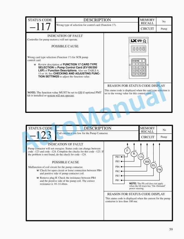
- 13.3. Fault Codes
- 14. RM1101-(12-2015)-US-EN
- 14.1. Series Code / Model Designation Reference Table
- 14.2. General
- 14.3. Fault Codes
- 15. RM1109-(07-2014)-UK-EN
- 16. RM1109-(07-2014)-US-EN
- 17. RM1114-(07-2014)-UK-EN
- 18. RM1114-(07-2014)-US-EN
- 19. RM1116-(11-2014)-UK-EN
- 20. RM1116-(11-2014)-US-EN
- 21. RM1117-(01-2012)-UK-EN
- 21.1. Parking Brake
- 21.2. Safety Precautions Maintenance and Repair
- 21.3. General
- 21.4. Description and Operation
- 21.5. Parking Brake Valve Replacement
- 21.6. Clean and Inspect
- 21.7. Install
- 21.8. Parking Brake Caliper Repair
- 21.9. Disassemble
- 21.10. Inspect
- 21.11. Install
- 21.12. Bleed Brakes
- 21.13. Brake Pad Repair
- 21.14. Inspect
- 21.15. Install
- 21.16. Seals Repair
- 21.17. Install
- 21.18. Specifications
- 21.19. Torque Requirements
- 21.20. Wear Limits
- 21.21. Lining to Disc Clearance
- 21.22. Troubleshooting
- 21.23. Table 1. Brake Pad Adjustment
- 21.24. Table 2. Torque Requirements
- 21.25. Table 3. Wear Limits
- 21.26. Table 4. Lining to Disc Clearance
- 22. RM1117-(01-2012)-US-EN
- 22.1. Parking Brake
- 22.2. Safety Precautions Maintenance and Repair
- 22.3. General
- 22.4. Description and Operation
- 22.5. Parking Brake Valve Replacement
- 22.6. Clean and Inspect
- 22.7. Install
- 22.8. Parking Brake Caliper Repair
- 22.9. Disassemble
- 22.10. Inspect
- 22.11. Install
- 22.12. Bleed Brakes
- 22.13. Brake Pad Repair
- 22.14. Inspect
- 22.15. Install
- 22.16. Seals Repair
- 22.17. Install
- 22.18. Specifications
- 22.19. Torque Requirements
- 22.20. Wear Limits
- 22.21. Lining to Disc Clearance
- 22.22. Troubleshooting
- 22.23. Table 1. Brake Pad Adjustment
- 22.24. Table 2. Torque Requirements
- 22.25. Table 3. Wear Limits
- 22.26. Table 4. Lining to Disc Clearance
- 23. RM1160-(09-2014)-UK-EN
- 24. RM1160-(09-2014)-US-EN
- 25. RM1171-(11-2014)-UK-EN
- 26. RM1171-(11-2014)-US-EN
- 27. RM1233-(06-2009)-UK-EN
- 27.1. Hydraulic Plate
- 27.2. Safety Precautions Maintenance and Repair
- 27.3. General
- 27.4. Description and Operation
- 27.5. Hydraulic Oil Supply
- 27.6. Manifold, Section 1 of Hydraulic Plate
- 27.7. Main Control Valve, Section 2 of Hydraulic Plate
- 27.8. Description
- 27.9. Operation
- 27.10. Return Manifold, Section 3 of Hydraulic Plate
- 27.11. Brake Manifold, Section 4 of Hydraulic Plate
- 27.12. Cooling Circuit
- 27.13. Service Brake
- 27.14. Parking Brake
- 27.15. Flow Amplifier, Section 5 of Hydraulic Plate
- 27.16. Manifold, Section 1 of Hydraulic Plate
- 27.17. General
- 27.18. Valves and Pressure Switches
- 27.19. Main Control Valve, Section 2 of Hydraulic Plate
- 27.20. Disassemble
- 27.21. Auxiliary Section
- 27.22. Lift Section
- 27.23. Lift/Tilt Section
- 27.24. Clean and Inspect
- 27.25. Assemble
- 27.26. Auxiliary Section
- 27.27. Lift Section
- 27.28. Lift/Tilt Section
- 27.29. Install
- 27.30. Return Manifold, Section 3 of Hydraulic Plate
- 27.31. Disassemble
- 27.32. Clean and Inspect
- 27.33. Assemble
- 27.34. Install
- 27.35. Brake Manifold, Section 4 of Hydraulic Plate
- 27.36. Clean and Inspect
- 27.37. Install
- 27.38. Flow Amplifier, Section 5 of Hydraulic Plate
- 27.39. Hydraulic Hose Repair
- 27.40. Hydraulic Hose Identification
- 27.41. Torque Values
- 27.42. Measurements and Adjustments
- 27.43. Measurements
- 27.44. Adjustments
- 27.45. Troubleshooting
- 27.46. Table 1. Pilot Hoses
- 27.47. Table 2. Brake Hoses
- 27.48. Table 3. Auxiliary Hoses With Alternating P and T
- 27.49. Table 4. Steer Hoses
- 27.50. Table 5. Pressure Settings at 2100 RPM
- 28. RM1233-(06-2009)-US-EN
- 28.1. Hydraulic Plate
- 28.2. Safety Precautions Maintenance and Repair
- 28.3. General
- 28.4. Description and Operation
- 28.5. Hydraulic Oil Supply
- 28.6. Manifold, Section 1 of Hydraulic Plate
- 28.7. Main Control Valve, Section 2 of Hydraulic Plate
- 28.8. Description
- 28.9. Operation
- 28.10. Return Manifold, Section 3 of Hydraulic Plate
- 28.11. Brake Manifold, Section 4 of Hydraulic Plate
- 28.12. Cooling Circuit
- 28.13. Service Brake
- 28.14. Parking Brake
- 28.15. Flow Amplifier, Section 5 of Hydraulic Plate
- 28.16. Manifold, Section 1 of Hydraulic Plate
- 28.17. General
- 28.18. Valves and Pressure Switches
- 28.19. Main Control Valve, Section 2 of Hydraulic Plate
- 28.20. Disassemble
- 28.21. Auxiliary Section
- 28.22. Lift Section
- 28.23. Lift/Tilt Section
- 28.24. Clean and Inspect
- 28.25. Assemble
- 28.26. Auxiliary Section
- 28.27. Lift Section
- 28.28. Lift/Tilt Section
- 28.29. Install
- 28.30. Return Manifold, Section 3 of Hydraulic Plate
- 28.31. Disassemble
- 28.32. Clean and Inspect
- 28.33. Assemble
- 28.34. Install
- 28.35. Brake Manifold, Section 4 of Hydraulic Plate
- 28.36. Clean and Inspect
- 28.37. Install
- 28.38. Flow Amplifier, Section 5 of Hydraulic Plate
- 28.39. Hydraulic Hose Repair
- 28.40. Hydraulic Hose Identification
- 28.41. Torque Values
- 28.42. Measurements and Adjustments
- 28.43. Measurements
- 28.44. Adjustments
- 28.45. Troubleshooting
- 28.46. Table 1. Pilot Hoses
- 28.47. Table 2. Brake Hoses
- 28.48. Table 3. Auxiliary Hoses With Alternating P and T
- 28.49. Table 4. Steer Hoses
- 28.50. Table 5. Pressure Settings at 2100 RPM
- 29. RM1234-(07-2007)-UK-EN
- 29.1. Instrument Panel Indicators and Senders
- 29.2. Safety Precautions Maintenance and Repair
- 29.3. General
- 29.4. Description
- 29.5. General
- 29.6. Instrument Panel Meters, Indicators, and LCD Display
- 29.7. Connector
- 29.8. Seat Switch Logic
- 29.9. Central Warning Light Output
- 29.10. Buzzer Output
- 29.11. Instrument Panel Component Replacement
- 29.12. Instrument Panel
- 29.13. Replace
- 29.14. Sender Replacement
- 29.15. Fuel Level Sender
- 29.16. Pressure Sender
- 29.17. Temperature Sender
- 29.18. Low Coolant Sender
- 29.19. Vacuum Switch
- 29.20. Crankshaft Position Sensor
- 29.21. Table 1. Instrument Panel and Indicators
- 29.22. Table 2. Pin Description
- 29.23. Table 3. Sender Description
- 30. RM1234-(07-2007)-US-EN
- 30.1. Instrument Panel Indicators and Senders
- 30.2. Safety Precautions Maintenance and Repair
- 30.3. General
- 30.4. Description
- 30.5. General
- 30.6. Instrument Panel Meters, Indicators, and LCD Display
- 30.7. Connector
- 30.8. Seat Switch Logic
- 30.9. Central Warning Light Output
- 30.10. Buzzer Output
- 30.11. Instrument Panel Component Replacement
- 30.12. Instrument Panel
- 30.13. Replace
- 30.14. Sender Replacement
- 30.15. Fuel Level Sender
- 30.16. Pressure Sender
- 30.17. Temperature Sender
- 30.18. Low Coolant Sender
- 30.19. Vacuum Switch
- 30.20. Crankshaft Position Sensor
- 30.21. Table 1. Instrument Panel and Indicators
- 30.22. Table 2. Pin Description
- 30.23. Table 3. Sender Description
- 31. RM1236-(03-2007)-UK-EN
- 31.1. Diagrams
- 31.2. Safety Precautions Maintenance and Repair
- 32. RM1236-(03-2007)-US-EN
- 32.1. Diagrams
- 32.2. Safety Precautions Maintenance and Repair
- 33. RM1237-(06-2011)-UK-EN
- 33.1. Periodic Maintenance
- 33.2. Safety Precautions Maintenance and Repair
- 33.3. General
- 33.4. Serial Number Data
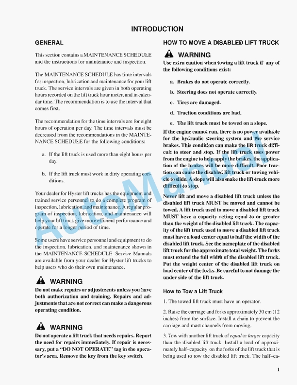
- 33.5. How to Move Disabled Lift Truck
- 33.6. How to Tow Lift Truck
- 33.7. How to Put Lift Truck on Blocks
- 33.8. How to Raise Drive Tires
- 33.9. How to Raise Steering Tires
- 33.10. How to Clean a Lift Truck
- 33.11. Maintenance Schedule
- 33.12. Spreader Maintenance
- 33.13. Maintenance Procedures Every 8 Hours or Daily
- 33.14. How to Make Checks With the Engine Stopped
- 33.15. Warning and Safety Labels
- 33.16. Wheels, Tires and Tire Pressure
- 33.17. Wheel Nuts
- 33.18. Mast, Carriage, and Attachments
- 33.19. Header Hose Assembly
- 33.20. Pre-Cleaner for Air Filter
- 33.21. Hydraulic Tank Breather
- 33.22. Fuel, Oil, or Coolant Leaks
Rate this product
You may also like
Hyster Service Manual PDF
$30.00
Hyster Service Manual PDF
Hyster 2.6L, 3.0L, 3.3L Yanmar Diesel Engines Maintenance And Repair
$30.00


%20Maintenance%20Schedule&url=https://automanual.net/doc/hyster-c098-e3-50-5-50xl-e4-50xls-maintenance-schedule/&media=https://automanual.net/wp-content/uploads/2026/01/hyster-c098-e350-550xl-e450xls-maintenance-schedule-1.jpg)
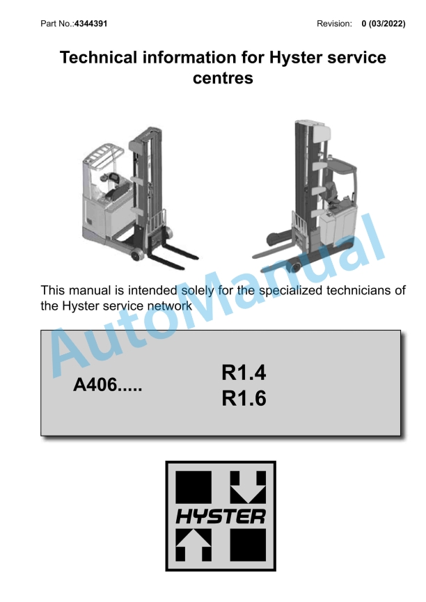
%20Service%20Manual&url=https://automanual.net/doc/hyster-a406-r1-4-r1-6-service-manual/&media=https://automanual.net/wp-content/uploads/2026/01/hyster-a406-r14-r16-service-manual-1.jpg)
%20Service%20Manual&url=https://automanual.net/doc/hyster-c098-e3-50-5-50xl-service-manual/&media=https://automanual.net/wp-content/uploads/2026/01/hyster-c098-e350-550xl-service-manual-1.jpg)
%20Service%20Manual&url=https://automanual.net/doc/hyster-c098-e70-120xl-service-manual/&media=https://automanual.net/wp-content/uploads/2026/01/hyster-c098-e70-120xl-service-manual-1.jpg)
%20Service%20Manual&url=https://automanual.net/doc/hyster-b418-p1-6-p1-8-p2-0-p2-2-service-manual/&media=https://automanual.net/wp-content/uploads/2026/01/hyster-b418-p16-p18-p20-p22-service-manual-1.jpg)
%20Service%20Manual&url=https://automanual.net/doc/hyster-b160-j25-35bs-service-manual/&media=https://automanual.net/wp-content/uploads/2026/01/hyster-b160-j25-35bs-service-manual-1.jpg)
- Claas
- Grove
- New Holland
- Komatsu
- Kubota
- John Deere
- Linde
- Bomag
- CASE
- Clark
- JCB
- Jungheinrich
- Linde
- Yale
- Yanmar
- Manitou
- Manitowoc
- CNH
- Doosan
- Fiatagri
- Fiatallis
- Fiatallis Other Manual PDF
- Flexi Coil
- Ford New Holland
- Ford New Holland Other Manual PDF
- Huyndai
- Hypac
- Hyster
- Hyster Service Manual PDF
- Isuzu
- Kobelco
- Kohler
- Krupp
- Lombardini
- Mahindra
- Nuvera
- Perkins
- Sperry New Holland
- Utilev
- Versatile
- ZF