- Claas
- Grove
- New Holland
- Komatsu
- Kubota
- John Deere
- Linde
- Bomag
- CASE
- Clark
- JCB
- Jungheinrich
- Linde
- Yale
- Yanmar
- Manitou
- Manitowoc
- CNH
- Doosan
- Fiatagri
- Fiatallis
- Fiatallis Other Manual PDF
- Flexi Coil
- Ford New Holland
- Ford New Holland Other Manual PDF
- Huyndai
- Hypac
- Hyster
- Hyster Service Manual PDF
- Isuzu
- Kobelco
- Kohler
- Krupp
- Lombardini
- Mahindra
- Nuvera
- Perkins
- Sperry New Holland
- Utilev
- Versatile
- ZF


Hyster Operator Cab Service Manual 4278318
$30.00
- Type Of Manual: Service Manual
- Manual ID: 4278318
- Number of Pages: 911
- Size: 63.8MB
- Format: PDF
Category: Hyster Service Manual PDF
-
Model List:
- Operator Cab
- 1. RM2325-(10-2020)-UK-EN
- 1.1. Series Code / Model Designation Reference Table
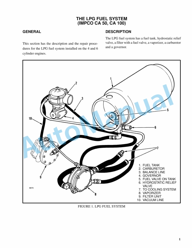
- 1.2. General
- 1.2.1. Precautions
- 1.3. Section 1 – Cab Repair
- 1.3.1. Operators Cab Assembly
- 1.3.2. Cab Tilt and Auto Tip-Up System
- 1.3.3. Cab Windows
- 1.3.4. Cab Door Assembly
- 1.3.5. Steering Wheel and Steering Column Assembly
- 1.3.6. Power Assist Armrest
- 1.3.7. Armrest Components
- 1.3.8. Display Replacement
- 1.3.9. Seat Assembly
- 1.3.10. Cab Interior
- 1.3.11. Accessories
- 1.3.12. Checks and Adjustments
- 1.3.13. Hydraulic Hose Torque Procedure
- 1.4. Section 2 – Cab Heater and Air Conditioner Repair
- 1.4.1. Heater/Air Conditioner Assembly
- 1.4.2. Heater/Air Conditioner Parts
- 1.4.3. Filtration
- 1.4.4. Air Conditioning Technical Detail
- 1.4.5. Maintenance, Service and Repairs
- 2. RM2326-(09-2020)-UK-EN
- 2.1. Series Code / Model Designation Reference Table
- 2.2. General
- 2.2.1. Precautions
- 2.3. Cooling System
- 2.3.1. Cooling Core Assembly
- 2.4. Cooling System Components
- 2.4.1. Cooling Fan (Tier 3/4F)
- 2.4.2. Cooling Fan and Fan Hydraulic Motor (Stage V)
- 2.5. Checks and Adjustments
- 2.5.1. Cooling System Checks
- 3. RM2328-(09-2020)-UK-EN
- 3.1. Series Code / Model Designation Reference Table
- 3.1.1. General
- 3.1.2. Precautions
- 3.2. Section 1 – Hydraulic System Repair
- 3.2.1. Main Control Valve
- 3.2.2. Priority Valve (A)
- 3.2.3. Check Valve (K)
- 3.2.4. Check Valve (I)
- 3.2.5. Check Valve (Q)
- 3.2.6. Screen Cartridge (O)
- 3.2.7. Shuttle Valves (L) and (M)
- 3.2.8. Logic Valve (N)
- 3.2.9. Full Flow Relief Valve (C) (Relief Spool)
- 3.2.10. Pilot Supply Valve (F)
- 3.2.11. Load Sense (LS) Relief Valve (H) and Full Flow Relief Valve (G)
- 3.2.12. Lift Pressure Selector Valve (B) or Load Sense Selector Valve (D)
- 3.2.13. d Pump Selector Valve (E)
- 3.2.14. Electrical Actuation Module
- 3.2.15. Emergency Lowering Valve (Left Slice Only)
- 3.2.16. Counterbalance Valve Manifold
- 3.2.17. Variable Displacement Pump (Primary and Secondary)
- 3.2.18. Load Sense and Pressure Controller Valve on Pump
- 3.2.19. Lowering Control Valve
- 3.2.20. Side Shift and Power Pile Slope Valve Assembly (582LS, 584LD, 584LF)
- 3.2.21. Side Shift Valve Assembly (586TB, 588TB, 589TB)
- 3.2.22. Extension Valve Assembly
- 3.2.23. Lock Pin Valve Assembly (584LF Only)
- 3.2.24. Pilot Check Valve Assembly
- 3.2.25. Hydraulic Block Assembly (582LS Only)
- 3.2.26. Hydraulic Tank
- 3.2.27. Hydraulic Checks and Adjustments
- 3.2.28. Hydraulic Hose Torque Procedure
- 3.2.29. Hydraulic System Torque Specifications
- 3.3. Section 2 – Steering System Hydraulics Repair
- 3.3.1. Steering Control Unit
- 3.3.2. Steering Cylinder
- 3.3.3. Steering System Torque Specifications
- 3.4. Section 3 – Brake System Hydraulics Repair
- 3.4.1. Brake Treadle Valve
- 3.4.2. Accumulator
- 3.4.3. Parking Brake
- 3.4.4. Brake Flow Distribution Manifold
- 3.4.5. Brake Control Manifold
- 3.4.6. Brake System Checks and Adjustments
- 3.4.7. Brake System Torque Specifications
- 3.5. Section 4 – Cylinder Repair
- 3.5.1. Front End Cylinders
- 3.5.2. Cab Tilt Cylinder
- 3.5.3. Extendable Container Attachment Cylinders
- 3.5.4. Cylinder Torque Specifications
- 4. RM2329-(09-2020)-UK-EN
- 4.1. Series Code / Model Designation Reference Table
- 4.2. Section 1 – Electrical
- 4.2.1. General Fault Finding
- 4.2.2. Harnesses and Connectors
- 4.2.3. CANbus Circuit
- 4.2.4. Greasing System Electrical
- 4.3. Section 2 – Controls
- 4.3.1. User Interface Display
- 4.3.2. Fault Codes
- 4.4. Section 3 – User Interface Display
- 4.4.1. Navigation Key
- 4.4.2. Startup Sequence
- 4.4.3. Home Screen
- 4.4.4. Logging in
- 4.4.5. View the fault log
- 4.4.6. View the hardware and software versions
- 4.4.7. Calibrations
- 4.4.8. Diagnostics Menu
- 4.4.9. Settings
- 4.4.10. Display Flow Chart
- 5. RM2330-(09-2020)-UK-EN
- 5.1. Series Code / Model Designation Reference Table
- 5.2. General
- 5.3. Greasing System
- 5.3.1. Grease Pump Assembly
- 5.4. Greasing System Components
- 5.4.1. Precautions
- 5.4.2. Grease Line Identification
- 5.4.3. Grease Reservoir
- 5.4.4. Refilling the Grease Reservoir
- 5.4.5. Test Cycles Using the Button on the Pump
- 5.4.6. Bleeding the Pump
- 5.4.7. Bleeding the System
- 5.5. Checks and Adjustments
- 5.5.1. Test Procedures
- 5.5.2. Adjusting Greasing Hoses on Tie Rod Pins
- 5.6. Technical and Operation Data
- 5.6.1. Pump Unit
- 5.6.2. Grease Recommendations
- 5.6.3. Electrical
- 5.6.4. Greasing System Operation
- 5.7. Torque Specifications
- 6. RM2331-(09-2020)-UK-EN
- 6.1. Series Code / Model Designation Reference Table
- 6.2. General
- 6.2.1. Precautions
- 6.3. Section 1 – Extendable Empty Container Attachment Repair
- 6.3.1. Extendable Empty Container Attachment Assembly
- 6.3.2. Extendable Empty Container Attachment Components
- 6.3.3. Adjustments
- 6.3.4. Electrical Component Checks
- 6.4. Section 2 – Mast Repair
- 6.4.1. Mast Assembly
- 6.4.2. Mast Components
- 6.4.3. Mast Checks and Adjustments
- 6.5. Torque Specifications
- 6.5.1. Hydraulic Hose Torque Procedure
- 7. RM2332-(10-2020)-UK-EN
- 7.1. Series Code / Model Designation Reference Table
- 7.2. General
- 7.3. Weights and Dimensions
- 7.4. Loading Procedures
- 7.4.1. Loading A Truck on a Transport
- 7.4.2. Loading Disassembled Components
- 7.5. Unloading Procedures
- 7.5.1. Unloading A Truck From Transport
- 7.5.2. Unloading Disassembled Components
- 7.6. Moving and Towing
- 7.6.1. Moving a Disabled Lift Truck
- 7.7. Safety Procedures When Working Near The Mast
- 7.7.1. When Working Near The Mast Always
- 7.7.2. Before Starting Repairs To The Hydraulic System Always
- 7.8. Truck Assembly
- 7.8.1. Mast, Tilt Cylinders, and Lift Cylinders Installation
- 7.8.2. Installing the Attachment
- 7.8.3. Installing the Exhaust Extension
- 7.8.4. Installing the Auto Tip-Up AC Condenser
- 7.8.5. Installing the Cab Lights
- 7.8.6. Installing the Raised Cab Tower
- 7.8.7. Lubrication
- 7.9. General Checks After Assembly
- 7.9.1. Plumbing Check
- 7.9.2. Lubrication Check
- 7.9.3. Fluid Level Check
- 7.9.4. Functionality Check
- 7.9.5. Literature Package Check
- 7.9.6. Cleaning
- 7.10. Wheels and Tires
- 7.10.1. Remove Wheels From Lift Truck
- 7.10.2. Pneumatic Tires
- 7.10.3. Adding Air Pressure to Tires
- 7.10.4. Solid Rubber Tires
- 7.10.5. Install Wheels on Lift Truck
- 7.11. Pre-Delivery
- 7.11.1. Perform Pre-Delivery Inspection
- 7.12. Delivery
- 7.12.1. Instructions Operating Manual
- 7.12.2. Instructions Daily Maintenance
- 7.12.3. Handing Over Truck
- 8. RM2333-(09-2020)-UK-EN
- 8.1. Series Code / Model Designation Reference Table
- 8.2. General
- 8.2.1. Precautions
- 8.3. Main Components
- 8.3.1. Frame Covers
- 8.3.2. Floor Plates, Handrails, and Steps
- 8.3.3. Counterweight
- 8.3.4. Heat Shield, Mercedes-Benz Stage V
- 8.3.5. Label Replacement
- 9. RM2334-(09-2020)-UK-EN
- 9.1. Series Code / Model Designation Reference Table
- 9.2. Capacities
- 9.3. Container Attachment Weights
- 9.4. Counterweight Weights
- 9.5. Electrical System
- 9.6. Engine Specifications
- 9.7. Hydraulic System
- 9.8. Lift Truck Weights
- 9.9. Mast Speeds
- 9.10. Mast Weights
- 9.11. Tire Sizes
- 9.12. Torque Specifications, General
- 9.12.1. Electrical
- 9.12.2. Counterweight
- 9.12.3. Counterweight
- 9.12.4. Drive Axle
- 9.12.5. Planetary Gear Carrier
- 9.12.6. Steering Axle
- 9.12.7. Wheel Bearing Adjusting Nut, Axletech
- 9.12.8. Transmission
- 9.12.9. Torque Converter
- 9.12.10. Steering
- 9.12.11. Wheel Nuts
- 9.12.12. Attachment
- 9.13. Torque Specifications Engines
- 10. RM2335-(10-2020)-UK-EN
- 10.1. Series Code / Model Designation Reference Table
- 10.2. Electrical Schematics 8-11T ECH Stage V
- 10.3. Hydraulic Schematics 8-11T ECH
- 11. RM2336-(10-2020)-UK-EN
- 11.1. Series Code / Model Designation Reference Table
- 11.2. General
- 11.2.1. Serial Number Data
- 11.3. Truck Handling Procedures
- 11.3.1. Moving and Towing a Lift Truck
- 11.3.2. Putting a Lift Truck on Blocks
- 11.3.3. Cleaning a Lift Truck
- 11.4. Safety Procedures Before Starting Maintenance
- 11.4.1. Making Checks From the Driver Seat With Engine Running
- 11.4.2. Wait Before Disconnecting Battery
- 11.5. Periodic Maintenance Schedule
- 11.5.1. Daily Inspection
- 11.5.2. Initial Inspection
- 11.5.3. Periodic Maintenance
- 11.6. Container Attachment ELME 580 SeriesPeriodic Maintenance Schedule
- 11.6.1. Periodic Maintenance
- 11.7. Periodic Maintenance Procedures
- 11.7.1. Air Conditioning System
- 11.7.2. Attachment
- 11.7.3. Automatic Greasing System (OPTIONAL)
- 11.7.4. Bearing Pads
- 11.7.5. Brake Cooling Filter
- 11.7.6. Brake System Accumulator
- 11.7.7. Cab Air Filter
- 11.7.8. Container Locking System
- 11.7.9. Control Levers, Switches and Pedals
- 11.7.10. Cooling System
- 11.7.11. Crankcase Breather Element (Cummins Tier 4F/Stage IV Only)
- 11.7.12. Crankcase Breather Element (Mercedes-Benz Stage V Only)
- 11.7.13. Diesel Exhaust Fluid (DEF) System
- 11.7.14. Drive Axle And Differential
- 11.7.15. Drive Shaft
- 11.7.16. Engine Air Filter
- 11.7.17. Engine Air Intake Piping and Charge Air Piping
- 11.7.18. Engine And Transmission Mounts
- 11.7.19. Engine Drive Belt, Tensioner and Pulley
- 11.7.20. Engine Oil
- 11.7.21. Engine Valve Adjustment (Cummins Tier 3/Stage IIIA and Tier 4F/Stage IV Only)
- 11.7.22. Engine Valve Adjustment (Mercedes-Benz Stage V)
- 11.7.23. Fault Codes
- 11.7.24. Frame, Mast, Carriage and Attachment
- 11.7.25. Fuel, Oil, DEF, or Coolant Leaks
- 11.7.26. Fuel/Water Separator and Fuel Filter
- 11.7.27. Header Hose Assembly
- 11.7.28. Horn, Lights, Alarms and Control System
- 11.7.29. Hydraulic System Oil
- 11.7.30. Hydraulic Tank Breather
- 11.7.31. Hydraulic Tank Return Filter
- 11.7.32. Inching Pedal Sensor Calibration
- 11.7.33. Lift Chains
- 11.7.34. Lift System Accumulator
- 11.7.35. Load Rollers
- 11.7.36. Mast, Carriage and Attachment Controls
- 11.7.37. Mast Pivot Pins
- 11.7.38. Operator Presence System
- 11.7.39. Operator Restraint System
- 11.7.40. Parking and Service Brakes
- 11.7.41. Powered Pile Slope Cylinder Bearings
- 11.7.42. Radiator Assembly
- 11.7.43. Spreader Control System Signals
- 11.7.44. Steering Axle Grease Fittings
- 11.7.45. Steering System
- 11.7.46. Steer Wheel Hub Bearings
- 11.7.47. Tilt Cylinder Pivot Pins
- 11.7.48. Transmission
- 11.7.49. Vibration Damper (Viscous)
- 11.7.50. Warning and Safety Labels
- 11.7.51. Windows and Mirrors
- 11.7.52. Windshield Washer Fluid Level
- 11.7.53. Wheels and Tires
- 11.8. Capacities and Specifications
- 11.8.1. Approved Fuel and Engine Oil
- 11.8.2. Approved Oils, Fluids and Grease
- 11.8.3. Engine Oil Viscosity
- 11.8.4. Lift Chain Lubricant Requirements
- 11.8.5. Electrical Components
- 12. RM2338-(10-2020)-UK-EN
- 12.1. Series Code / Model Designation Reference Table
- 12.2. General
- 12.3. Section 1 – Troubleshooting
- 12.3.1. Troubleshooting – Symptom Based
- 12.4. Section 2 – Error Codes
- 12.4.1. Armrest
- 12.4.2. Engine (Cummins)
- 12.4.3. Engine (Mercedes-Benz)
- 12.4.4. Greasing (Frame)
- 12.4.5. Heating Ventilation and Air Conditioning (HVAC)
- 12.4.6. Hydraulic Controller
- 12.4.7. Smart Antenna
- 12.4.8. Transmission (ZF)
- 13. UT80-100P-U-SM-EN-(05-2017)-SECTION 1 POWER SYSTEM
Rate this product
You may also like
Hyster Service Manual PDF
$30.00
Hyster Service Manual PDF
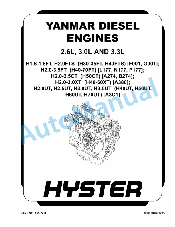
Hyster 2.6L, 3.0L, 3.3L Yanmar Diesel Engines Maintenance And Repair
$30.00
%20Maintenance%20Schedule&url=https://automanual.net/doc/hyster-c098-e3-50-5-50xl-e4-50xls-maintenance-schedule/&media=https://automanual.net/wp-content/uploads/2026/01/hyster-c098-e350-550xl-e450xls-maintenance-schedule-1.jpg)
%20Service%20Manual&url=https://automanual.net/doc/hyster-c001-h1-25-1-75xl-service-manual/&media=https://automanual.net/wp-content/uploads/2026/01/hyster-c001-h125-175xl-service-manual-1.jpg)
%20Service%20Manual&url=https://automanual.net/doc/hyster-b168-j40-60xl-service-manual/&media=https://automanual.net/wp-content/uploads/2026/01/hyster-b168-j40-60xl-service-manual-1.jpg)
%20Service%20Manual&url=https://automanual.net/doc/hyster-c010-s1-50-2-00xms-service-manual/&media=https://automanual.net/wp-content/uploads/2026/01/hyster-c010-s150-200xms-service-manual-1.jpg)
%20Service%20Manual&url=https://automanual.net/doc/hyster-c002-s30-50c-service-manual/&media=https://automanual.net/wp-content/uploads/2026/01/hyster-c002-s30-50c-service-manual-1.jpg)
%20Service%20Manual&url=https://automanual.net/doc/hyster-c005-h60-90c-service-manual/&media=https://automanual.net/wp-content/uploads/2026/01/hyster-c005-h60-90c-service-manual-1.jpg)
%20Service%20Manual&url=https://automanual.net/doc/hyster-a406-r1-4-r1-6-service-manual/&media=https://automanual.net/wp-content/uploads/2026/01/hyster-a406-r14-r16-service-manual-1.jpg)
- Claas
- Grove
- New Holland
- Komatsu
- Kubota
- John Deere
- Linde
- Bomag
- CASE
- Clark
- JCB
- Jungheinrich
- Linde
- Yale
- Yanmar
- Manitou
- Manitowoc
- CNH
- Doosan
- Fiatagri
- Fiatallis
- Fiatallis Other Manual PDF
- Flexi Coil
- Ford New Holland
- Ford New Holland Other Manual PDF
- Huyndai
- Hypac
- Hyster
- Hyster Service Manual PDF
- Isuzu
- Kobelco
- Kohler
- Krupp
- Lombardini
- Mahindra
- Nuvera
- Perkins
- Sperry New Holland
- Utilev
- Versatile
- ZF