No products in the cart.
Return to shop
$30.00
Hyster Service Manual PDF
Hyster C098 (E3.50-5.50XL) Service Manual
Hyster C007 (H150-275HP150-200B) Service Manual
Hyster C001 (H25-35XL) Service Manual
Hyster B460 (K1.0M, K1.0H, K1.0H WP) Service Manual
Hyster C098 (E70-120XL) Service Manual
Hyster A406 Service Manual
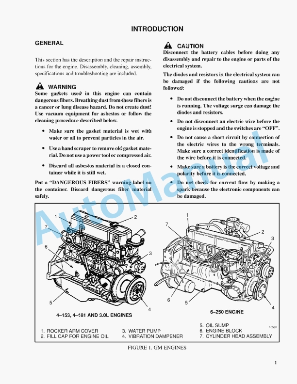
Hyster 4.3 Liter V-6 GM Engines Maintenance And Repair
Hyster B210 (N30AH) Service Manual
Hyster C004 (S3.00-5.50E) Service Manual
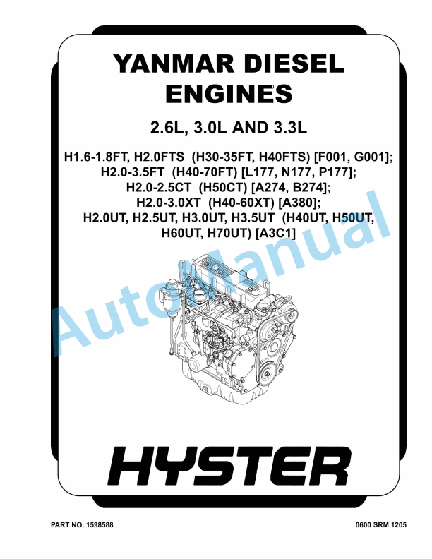
Hyster 2.6L, 3.0L, 3.3L Yanmar Diesel Engines Maintenance And Repair


%20Service%20Manual&url=https://automanual.net/doc/hyster-c098-e3-50-5-50xl-service-manual/&media=https://automanual.net/wp-content/uploads/2026/01/hyster-c098-e350-550xl-service-manual-1.jpg)
%20Service%20Manual&url=https://automanual.net/doc/hyster-c007-h150-275hp150-200b-service-manual/&media=https://automanual.net/wp-content/uploads/2026/01/hyster-c007-h150-275hp150-200b-service-manual-1.jpg)
%20Service%20Manual&url=https://automanual.net/doc/hyster-c001-h25-35xl-service-manual/&media=https://automanual.net/wp-content/uploads/2026/01/hyster-c001-h25-35xl-service-manual-1.jpg)
%20Service%20Manual&url=https://automanual.net/doc/hyster-b460-k1-0m-k1-0h-k1-0h-wp-service-manual/&media=https://automanual.net/wp-content/uploads/2026/01/hyster-b460-k10m-k10h-k10h-wp-service-manual-1.jpg)
%20Service%20Manual&url=https://automanual.net/doc/hyster-c098-e70-120xl-service-manual/&media=https://automanual.net/wp-content/uploads/2026/01/hyster-c098-e70-120xl-service-manual-1.jpg)
%20Service%20Manual&url=https://automanual.net/doc/hyster-b210-n30ah-service-manual/&media=https://automanual.net/wp-content/uploads/2026/01/hyster-b210-n30ah-service-manual-1.jpg)
%20Service%20Manual&url=https://automanual.net/doc/hyster-c004-s3-00-5-50e-service-manual/&media=https://automanual.net/wp-content/uploads/2026/01/hyster-c004-s300-550e-service-manual-1.jpg)