 Frame And Main Components Service Manual 1")
 Frame And Main Components Service Manual 2")
 Frame And Main Components Service Manual 3")
 Frame And Main Components Service Manual 4")
 Frame And Main Components Service Manual 5")

Hyster Service Manual PDF
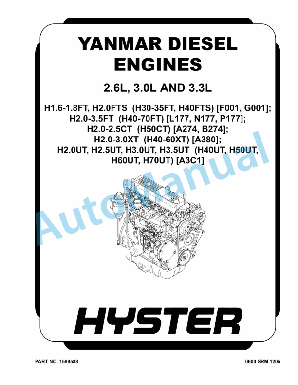
Hyster 2.6L, 3.0L, 3.3L Yanmar Diesel Engines Maintenance And Repair
$30.00

Hyster Service Manual PDF
Hyster C1.0 to R30XMF2 Guide Wire Installation Maintenance And Repair
$30.00
$30.00
Hyster Service Manual PDF
Hyster 2.6L, 3.0L, 3.3L Yanmar Diesel Engines Maintenance And Repair
Hyster Service Manual PDF
Hyster C1.0 to R30XMF2 Guide Wire Installation Maintenance And Repair
Hyster Service Manual PDF
%20Frame%20And%20Main%20Components%20Service%20Manual&url=https://automanual.net/doc/hyster-p2-0s-p2-5s-p3-0s-e439-frame-and-main-components-service-manual/&media=https://automanual.net/wp-content/uploads/2026/01/hyster-p20s-p25s-p30s-e439-frame-and-main-components-service-manual-1.jpg)
%20Service%20Manual&url=https://automanual.net/doc/hyster-c098-e3-50-5-50xl-service-manual/&media=https://automanual.net/wp-content/uploads/2026/01/hyster-c098-e350-550xl-service-manual-1.jpg)
%20Service%20Manual&url=https://automanual.net/doc/hyster-c001-h25-35xl-service-manual/&media=https://automanual.net/wp-content/uploads/2026/01/hyster-c001-h25-35xl-service-manual-1.jpg)
%20Service%20Manual&url=https://automanual.net/doc/hyster-b174-r30es-service-manual/&media=https://automanual.net/wp-content/uploads/2026/01/hyster-b174-r30es-service-manual-1.jpg)
%20Service%20Manual&url=https://automanual.net/doc/hyster-c098-e70-120xl-service-manual/&media=https://automanual.net/wp-content/uploads/2026/01/hyster-c098-e70-120xl-service-manual-1.jpg)
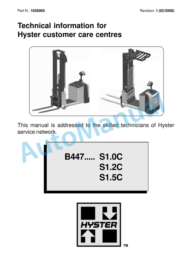
%20Service%20Manual&url=https://automanual.net/doc/hyster-b447-s1-0c-s1-2c-s1-5c-service-manual/&media=https://automanual.net/wp-content/uploads/2026/01/hyster-b447-s10c-s12c-s15c-service-manual-1.jpg)
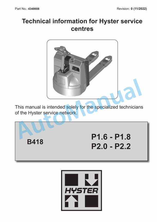
%20Service%20Manual&url=https://automanual.net/doc/hyster-b418-p1-6-p1-8-p2-0-p2-2-service-manual/&media=https://automanual.net/wp-content/uploads/2026/01/hyster-b418-p16-p18-p20-p22-service-manual-1.jpg)