No products in the cart.
Return to shop
$30.00
Hyster Service Manual PDF
Hyster C005 (H60-90C) Service Manual
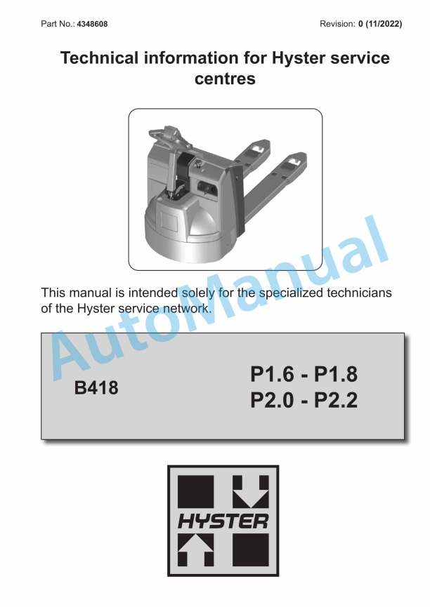
Hyster B418 (P1.6, P1.8, P2.0, P2.2) Service Manual
Hyster A3C5 J1.6-2.0UTT Service Manual
Hyster Battery Indicators Maintenance And Repair
Hyster Alternator With Regulator Maintenance And Repair
Hyster C1.0 to R30XMF2 Guide Wire Installation Maintenance And Repair
Hyster C004 (S3.00-5.50E) Service Manual
Hyster C001 (H25-35XL) Service Manual
Hyster C098 (E3.50-5.50XL) Service Manual
Hyster C007 (H150-275HP150-200B) Service Manual
 Motorized Hand Truck Service Manual 1")
 Motorized Hand Truck Service Manual 2")
 Motorized Hand Truck Service Manual 3")
 Motorized Hand Truck Service Manual 4")
 Motorized Hand Truck Service Manual 5")

%20Motorized%20Hand%20Truck%20Service%20Manual&url=https://automanual.net/doc/hyster-p30ut-a3d1-motorized-hand-truck-service-manual/&media=https://automanual.net/wp-content/uploads/2026/01/hyster-p30ut-a3d1-motorized-hand-truck-service-manual-1.jpg)
%20Service%20Manual&url=https://automanual.net/doc/hyster-c005-h60-90c-service-manual/&media=https://automanual.net/wp-content/uploads/2026/01/hyster-c005-h60-90c-service-manual-1.jpg)
%20Service%20Manual&url=https://automanual.net/doc/hyster-b418-p1-6-p1-8-p2-0-p2-2-service-manual/&media=https://automanual.net/wp-content/uploads/2026/01/hyster-b418-p16-p18-p20-p22-service-manual-1.jpg)
%20Service%20Manual&url=https://automanual.net/doc/hyster-c004-s3-00-5-50e-service-manual/&media=https://automanual.net/wp-content/uploads/2026/01/hyster-c004-s300-550e-service-manual-1.jpg)
%20Service%20Manual&url=https://automanual.net/doc/hyster-c001-h25-35xl-service-manual/&media=https://automanual.net/wp-content/uploads/2026/01/hyster-c001-h25-35xl-service-manual-1.jpg)
%20Service%20Manual&url=https://automanual.net/doc/hyster-c098-e3-50-5-50xl-service-manual/&media=https://automanual.net/wp-content/uploads/2026/01/hyster-c098-e350-550xl-service-manual-1.jpg)
%20Service%20Manual&url=https://automanual.net/doc/hyster-c007-h150-275hp150-200b-service-manual/&media=https://automanual.net/wp-content/uploads/2026/01/hyster-c007-h150-275hp150-200b-service-manual-1.jpg)