No products in the cart.
Return to shop
$30.00
JCB Service Manual PDF
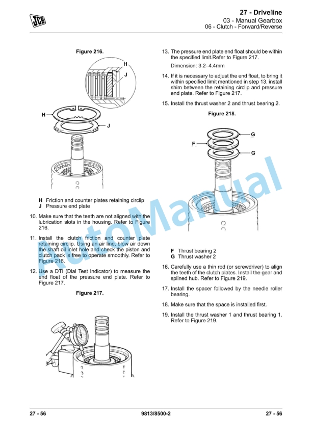
JCB 2DX Backhoe Loader Service Manual 9813-8500
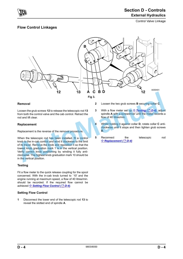
JCB 2155, 2170 Fastrac Service Manual 9803-8050
JCB 125, 135, 145, 150, 155, 185 Fastrac Service Manual 9803-8000
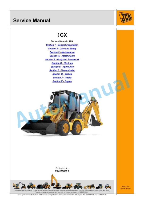
JCB 1CX, 208S Backhoe Loader Service Manual 9803-8550
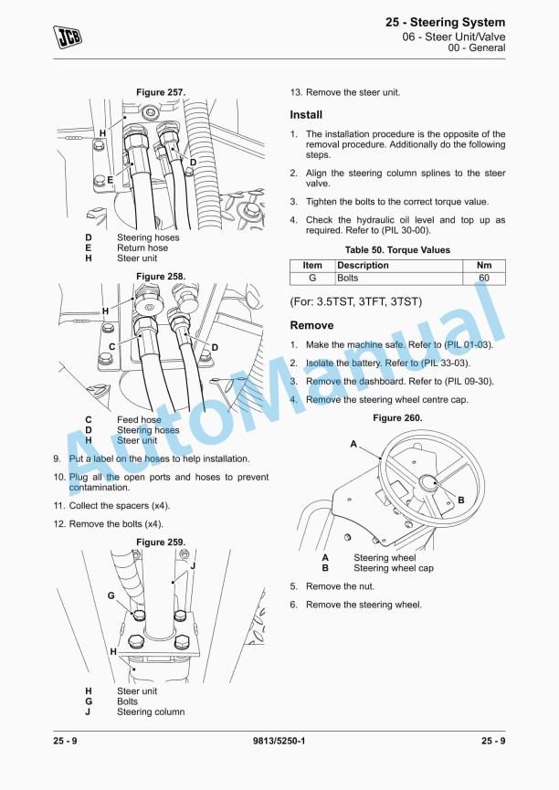
JCB 2TFT, 2THS, 2TST, 3.5TST, 3TFT, 3TST Service Manual 9813-5250
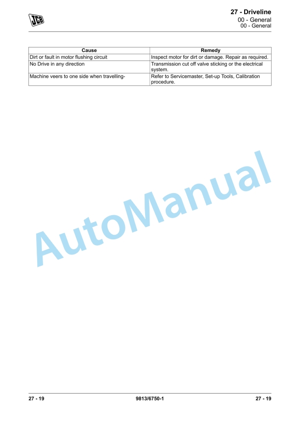
JCB 135, 155, 175, 190, 205 Skidsteer Loader Service Manual 9813-6750
JCB 1253, 1202, 1553, 1554 Liftall Service Manual 9813-1650
JCB 135 HD, 155 HD Skidsteer Loader Service Manual 9813-4450
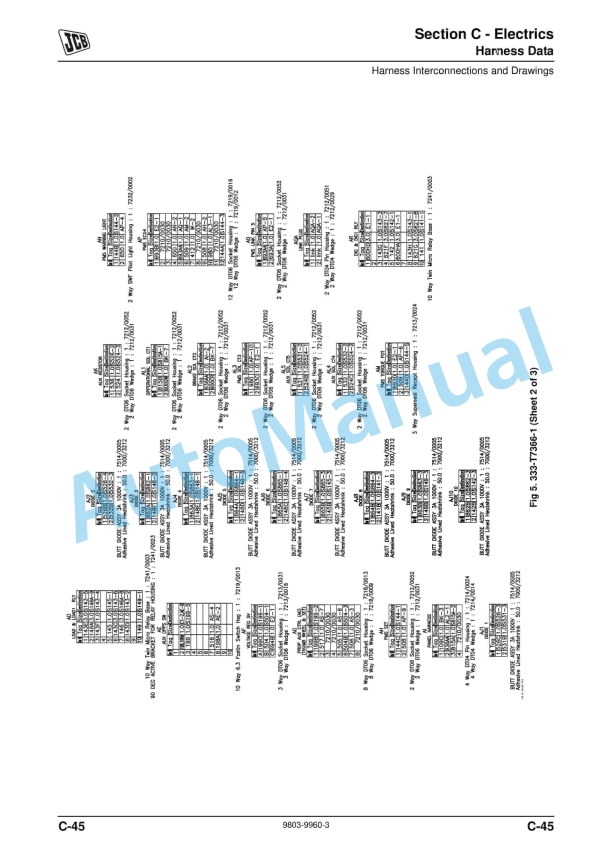
JCB 1CX Service Manual 9803-9960
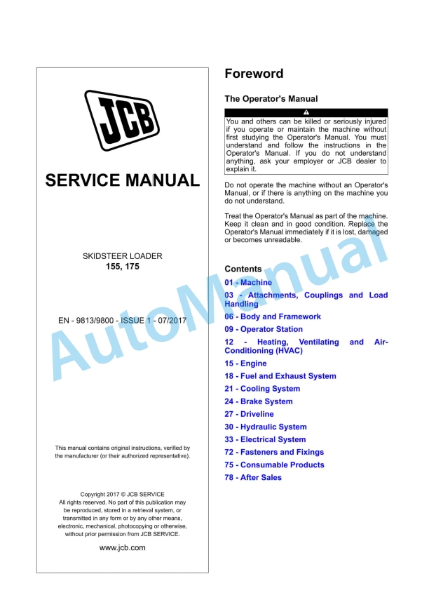
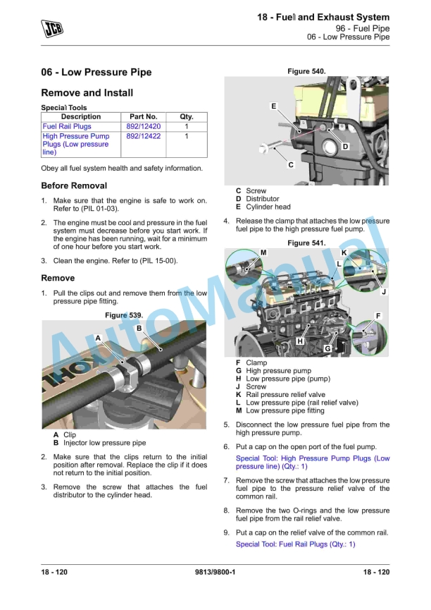
JCB 155, 175 Skidsteer Loader Service Manual 9813-9800


