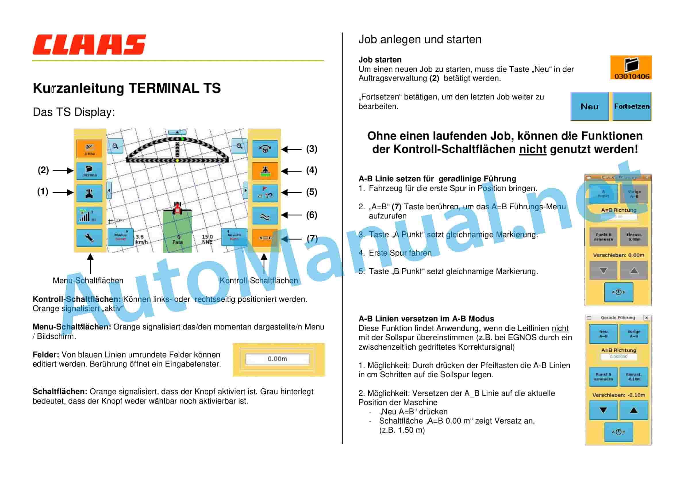
Claas STEERING SYSTEMS SENSORS MISCELLANEO (EAS) Digital solutions Operator Manual DE
$50.00
- Model: STEERING SYSTEMS SENSORS MISCELLANEO (EAS) Digital solutions
- Type Of Manual: Operator Manual
- Language: DE
- Format: PDF(s)
- Size: 164 MB
File List:
– 00 0018 530 0.pdf
– 00 0018 551 1.pdf
– 00 0018 583 4.pdf
– 00 0018 646 2.pdf
– 00 0018 651 1.pdf
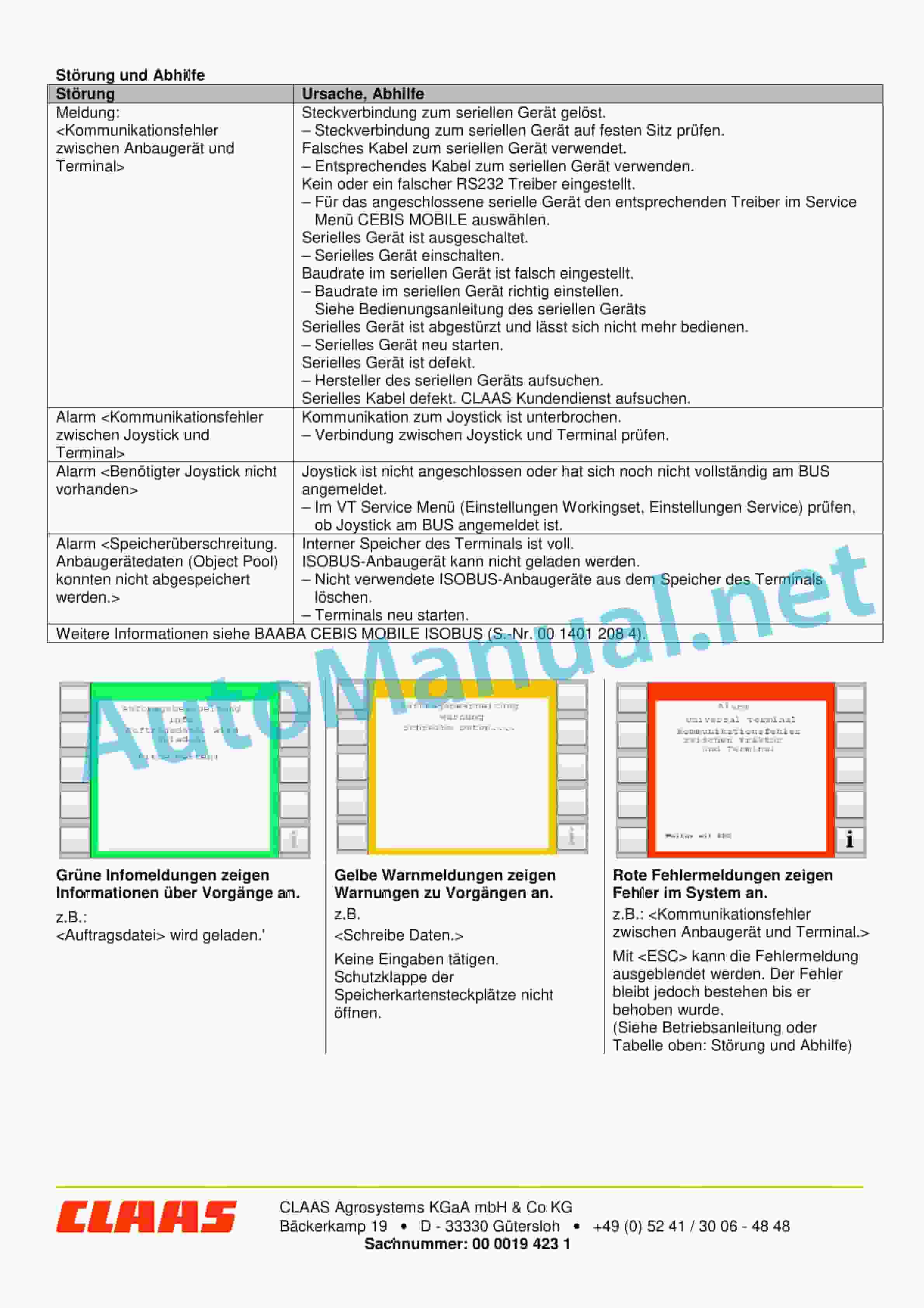
– 00 0019 423 1.pdf
– 00 0288 916 0.pdf
– 00 0290 485 0.pdf
– 00 0291 234 4.pdf
– 00 0292 584 4.pdf
– 00 0300 518 3.pdf
– 00 0301 050 0.pdf
– 00 0303 481 0.pdf
– 00 1400 061 1.pdf
– 00 1400 091 0.pdf
– 00 1400 216 1.pdf
– 00 1400 217 1.pdf
– 00 1400 253 0.pdf
– 00 1400 632 2.pdf
– 00 1400 634 3.pdf
– 00 1400 859 2.pdf
– 00 1401 207 1.pdf
– 00 1401 208 4.pdf
– 00 1402 752 1.pdf
– 00 1405 858 1.pdf
– 00 1420 000 2.pdf
– 00 1420 320 0.pdf
– 00 1420 345 0.pdf
– 00 2348 299 0.pdf
– 1400 252.pdf
00 0018 530 0.pdf
Table of Content:
1 BASELINE HD base station
2 Table of Contents
3 1 About these operating instructions
3.1 1.1 Notes on the instructions
4 2 Security
4.1 2.1 Intended use
4.2 2.2 Safety instructions
4.3 2.3 Safety instructions in these instructions
5 3 Product description
5.1 3.1 Overview and functionality
5.2 3.2 Type plates and identification numbers
6 4 Control and display elements
6.1 4.1 BASELINE HD
7 5 Technical data
7.1 5.1 BASELINE HD
8 6 Prepare product
8.1 6.1 BASELINE HD base station
8.2 6.2 Initial commissioning correction signal
9 7 Operation
9.1 7.1 BASELINE HD base station
9.2 7.2 Settings
10 8 Malfunction and remedy
10.1 8.1 Malfunction and remedy
11 9 Decommissioning and disposal
11.1 9.1 Decommissioning and disposal
12 10 technical terms and abbreviations
12.1 10.1 Terms and explanations
00 0018 551 1.pdf
Table of Content:
1 TELEMATICS website
2 Table of Contents
3 1 About these short operating instructions
3.1 1.1 Notes on the instructions
4 2 Security
4.1 2.1 Intended use
5 3 Product description
5.1 3.1 Overview and functionality
6 4 Control and display elements
6.1 4.1 TELEMATICS Overview
6.2 4.2 Menu structure
7 5 Technical data
7.1 5.1 TELEMATICS
7.2 5.2 Fleet View
8 6 Operation
8.1 6.1 TELEMATICS
8.2 6.2 Fleet View
00 0018 583 4.pdf
Table of Content:
1 EASY on board App
2 Table of Contents
3 1 Introduction
3.1 1.1 Notes on the instructions
3.2 1.2 Intended use
3.3 1.3 Software update
3.4 1.4 Malfunction and remedy
3.5 1.5 Technical terms and abbreviations
4 2 Security
4.1 2.1 Recognize warnings
4.2 2.2 Safety instructions
5 3 EASY on board App
5.1 3.1 Control and display elements
5.2 3.2 Operation
6 4 Documentation
6.1 4.1 Product description
6.2 4.2 Control and display elements
6.3 4.3 Create order
6.4 4.4 Documentation
7 5 ISO Terminal
7.1 5.1 Product description
7.2 5.2 Control and display elements
7.3 5.3 Programmable buttons
8 6 Settings
8.1 6.1 Control and display elements
8.2 6.2 Settings
9.1 7.1 Settings
00 0018 651 1.pdf
Table of Content:
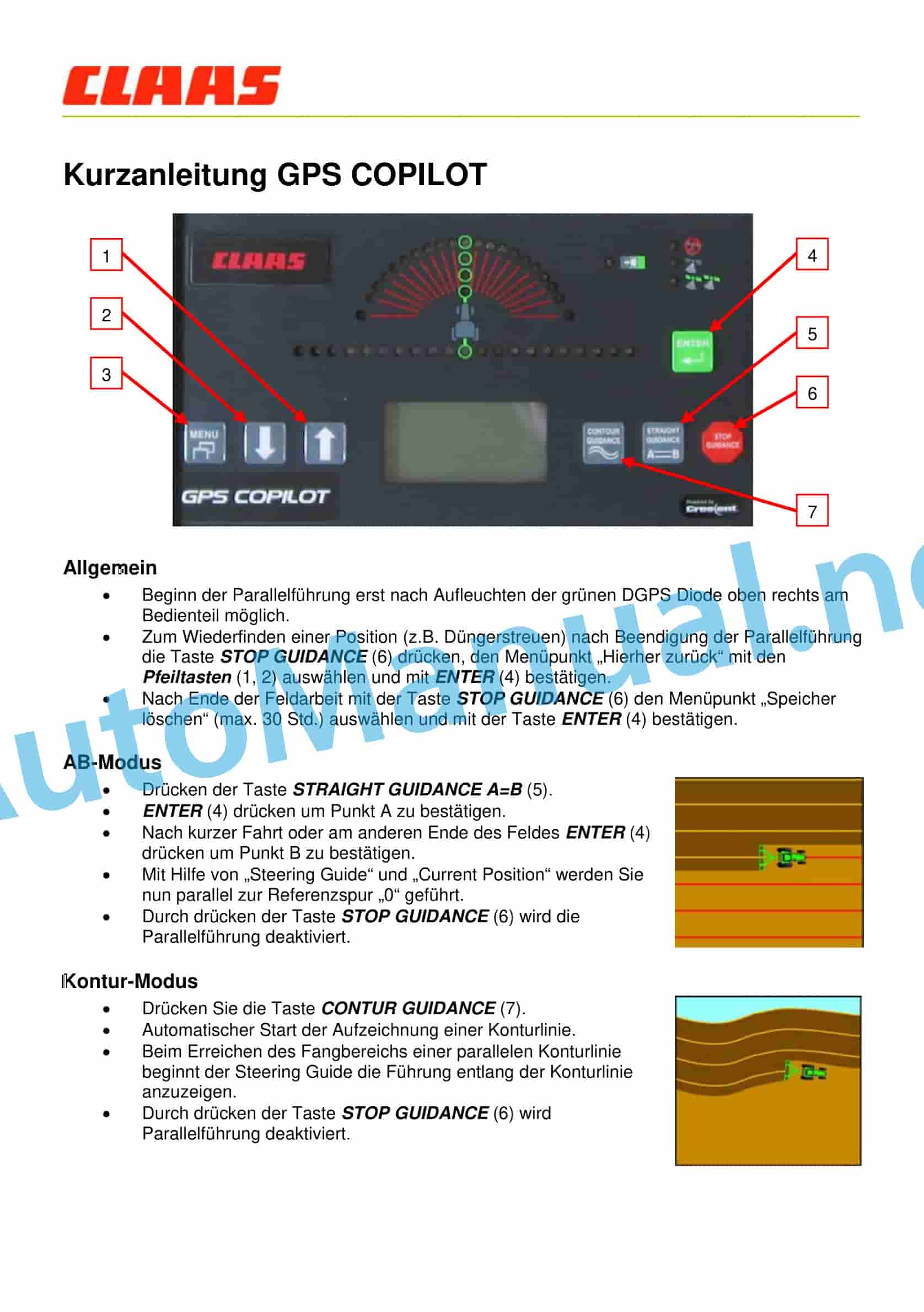
1 Quick guide GPS COPILOT
1.1 General
1.2 AB mode
1.3 Contour Mode
1.4 Change in working width
1.5 Change of signal type
1.6 Area measurement
1.7 Automatic A-B line shift
00 0288 916 0.pdf
Table of Content:
1 CEBIS MOBILE
2 CEBIS MOBILE
3 Table of Contents
4 1 Introduction
4.1 1.1 Notes on the instructions
5 2 Security
5.1 2.1 Recognize warnings
5.2 2.2 Safety instructions
6 3 Product description
6.1 3.1 Overview and functionality
6.2 3.2 Optional equipment
6.3 3.3 Type plates and identification numbers
7 4 Control and display elements
7.1 4.1 Operating concept
7.2 4.2 CEMOS
8 5 Prepare machine
8.1 5.1 Set machine before inventory
8.2 5.2 Learn inclination
8.3 5.3 Learn zero point of throughput
8.4 5.4 Setting secondary display area
9 6 Operation
9.1 6.1 Harvest
9.2 6.2 CRUISE PILOT
9.3 6.3 CEMOS AUTOMATIC
9.4 6.4 CEMOS DIALOG
00 0290 485 0.pdf
Table of Content:
2 1 Additions to the operating instructions
2.1 1.1 Introduction
2.2 1.2 Before initial commissioning
4 1 Supplements to operator’s manual
4.1 1.1 Introduction
4.2 1.2 Prior to initial operation
6 1 Complements la Notice d’utilisation
6.1 1.1 Introduction
6.2 1.2 Avant la first mise en service
8 1 Supplement to manual de es del primer uso
10 1 Supplement to the Libretto d’uso
10.1 1.1 Introduction
10.2 1.2 Prima della messa in campo iniziale
12 1 Doplnn k provoznmu nvodu
12.1 1.1 vod
12.2 1.2 Ped prvnm uvedenm do chodu
14 1 Kiegszts a kezelsi tmutatequipment
5.3 3.3 Type plates and identification numbers
6 4 Control and display elements
6.1 4.1 On-board computer CEBIS MOBILE
6.2 4.2 CEMOS
7 5 Operation
7.1 5.1 Preparing for work
7.2 5.2 On-board computer CEBIS MOBILE
7.3 5.3 CEMOS
7.4 5.4 CEMOS AUTOMATIC
00 0292 584 4.pdf
Table of Content:
1 COMMUNICATOR II
2 Table of Contents
3 1 Introduction
3.1 1.1 Notes on the instructions
3.2 1.2 Intended use
4 2 Security
4.1 2.1 Recognize warnings
4.2 2.2 Safety instructions
5 3 Product description
5.1 3.1 Overview and functionality
5.2 3.2 Type plates and identification numbers
6 4 Control and display elements
6.1 4.1 COMMUNICATOR II
6.2 4.2 Menu structure Universal Terminal (Service)
6.3 4.3 Menu structure order processing (task)
7 5 Technical data
7.1 5.1 COMMUNICATOR II
8 6 Prepare product
8.1 6.1 Switch off and secure the machine
9 7 Operation
9.1 7.1 Switch COMMUNICATOR II on/off
9.2 7.2 Programmable buttons
9.3 7.3 ISOBUS settings
9.4 7.4 Terminal Settings
9.5 7.5 Error message Universal Terminal
9.6 7.6 Order management
9.7 7.7 Order management settings
9.8 7.8 GPS information
9.9 7.9 Error message order management
10 8 Malfunction and remedy
10.1 8.1 Overview of faults
10.2 8.2 COMMUNICATOR II
11 9 Maintenance
11.1 9.1 Overview of maintenance intervals
11.2 9.2 COMMUNICATOR II
12 10 Decommissioning and disposal
12.1 10.1 General information
13 11 EC declaration of conformity
13.1 11.1 COMMUNICATOR II
14 12 technical terms and abbreviations
14.1 12.1 Technical terms and abbreviations
00 0300 518 3.pdf
Table of Content:
1 EASY on board App
2 Table of Contents
3 1 Introduction
3.1 1.1 General information
3.2 1.2 Intended use
4 2 Security
4.1 2.1 Recognize warnings
4.2 2.2 Safety instructions
5 3 Product description
5.1 3.1 Overview and functionality
5.2 3.2 Type plates and identification numbers
5.3 3.3 Information on the product
6 4 Control and display elements
6.1 4.1 CLAAS Wireless Interface (CWI)
6.2 4.2 CWI Setup App
7 5 Technical data
7.1 5.1 CLAAS Wireless Interface (CWI)
8 6 Prepare product
8.1 6.1 Install product
9 7 Operation
9.1 7.1 Initial commissioning
9.2 7.2 CWI Setup App
9.3 7.3 CWI Setup – Settings
9.4 7.4 CWI Setup – Advanced Settings
9.5 7.5 EASY on board App
10 8 Malfunction and remedy
10.1 8.1 Overview of faults
11 9 Maintenance
11.1 9.1 Maintenance tables
11.2 9.2 Tablet
12 10 Decommissioning and disposal
12.1 10.1 General information
13 11 EC declaration of conformity
13.1 11.1 CLAAS Wireless Interface (CWI)
14 12 technical terms and abbreviations
14.1 12.1 Terms and explanations
00 0301 050 0.pdf
Table of Content:
1 PROFI CAM 3
2 Table of Contents
3 1 Introduction
3.1 1.1 Notes on the instructions
3.2 1.2 Intended use
4 2 Security
4.1 2.1 Recognize warnings
4.2 2.2 Safety instructions
5 3 Product description
5.1 3.1 Overview and functionality
5.2 3.2 Type plates and identification number
5.3 3.3 Information on the product
6 4 Control and display elements
6.1 4.1 Camera system
6.2 4.2 Menu structure
7 5 Technical data
7.1 5.1 PROFI CAM
8 6 Prepare product
8.1 6.1 Switch off and secure the machine
8.2 6.2 Carry out before commissioning
9 7 Operation
9.1 7.1 Monitor
10 8 Malfunction and remedy
10.1 8.1 Electrics and electronics
11 9 Maintenance
11.1 9.1 Maintenance intervals
11.2 9.2 Camera system
12 10 Decommissioning and disposal
12.1 10.1 General information
13 11 technical terms and abbreviations
13.1 11.1 Abbreviations
00 0303 481 0.pdf
Table of Content:
1 PROFI CAM 4
2 Table of Contents
3 1 Introduction
3.1 1.1 Notes on the instructions
3.2 1.2 Intended use
4 2 Security
4.1 2.1 Recognize warnings
4.2 2.2 Safety instructions
5 3 Product description
5.1 3.1 Overview and functionality
5.2 3.2 Type plates and identification number
5.3 3.3 Information on the product
6 4 Control and display elements
6.1 4.1 Camera system
6.2 4.2 Menu structure
7 5 Technical data
7.1 5.1 PROFI CAM
8 6 Prepare product
8.1 6.1 Switch off and secure the machine
8.2 6.2 Carry out before commissioning
9 7 Operation
9.1 7.1 Monitor
10 8 Malfunction and remedy
10.1 8.1 Electrics and electronics
11 9 Maintenance
11.1 9.1 Maintenance intervals
11.2 9.2 Camera system
12 10 Decommissioning and disposal
12.1 10.1 General information
13 11 technical terms and abbreviations
13.1 11.1 Abbreviations
00 1400 091 0.pdf
Table of Content:
1 CULTI CAM
2 Table of Contents
3 1 About these operating instructions
3.1 1.1 Notes on the instructions
4 2 Security
4.1 2.1 Safety instructions
4.2 2.2 Safety instructions in these instructions
4.3 2.3 Safety devices
5 3 Product description
5.1 3.1 Overview and functionality
5.2 3.2 Optional equipment
5.3 3.3 Type plates and identification numbers
6 4 Control and display elements
6.1 4.1 COMMUNICATOR II
6.2 4.2 CULTI CAM
7 5 Technical data
7.1 5.1 COMMUNICATOR II
7.2 5.2 CULTI CAM
8 6 Prepare product
8.1 6.1 General information
8.2 6.2 Carry out before commissioning
8.3 6.3 Cultivation
8.4 6.4 CULTI CAM
9 7 Operation
9.1 7.1 Driving on the road
9.2 7.2 Switch COMMUNICATOR II on/off
9.3 7.3 COMMUNICATOR II Programmable buttons
9.4 7.4 COMMUNICATOR II ISOBUS settings
9.5 7.5 COMMUNICATOR II Terminal Settings
9.6 7.6 Work input
10 8 Malfunction and remedy
10.1 8.1 Overview of faults
11 9 Maintenance
11.1 9.1 General information
11.2 9.2 Maintenance instructions
12 10 Service
12.1 10.1 General information
13 11 Decommissioning and disposal
13.1 11.1 General information
14 12 technical terms and abbreviations
14.1 12.1 Terms and explanations
00 1400 216 1.pdf
Table of Content:
1 Short instructions for AGROCOM MAP for importing a new machine description
1.1! Attention: Read the instructions carefully and follow the instructions.
1.2 Step 1: On the PC in AGROCOM MAP write to memory card
1.3 Step 2: On CEBIS MOBILE create order with CROP SENSOR
1.4 Step 3: On the PC in AGROCOM MAP – Import of the machine description
00 1400 217 1.pdf
Table of Contns.
1.2 Step 1: On the PC in AGROCOM NET write to memory card
1.3 Step 2: On CEBIS MOBILE create order with CROP SENSOR
1.4 Step 3: On the PC in AGROCOM NET – Import of the machine description
00 1400 253 0.pdf
Table of Content:
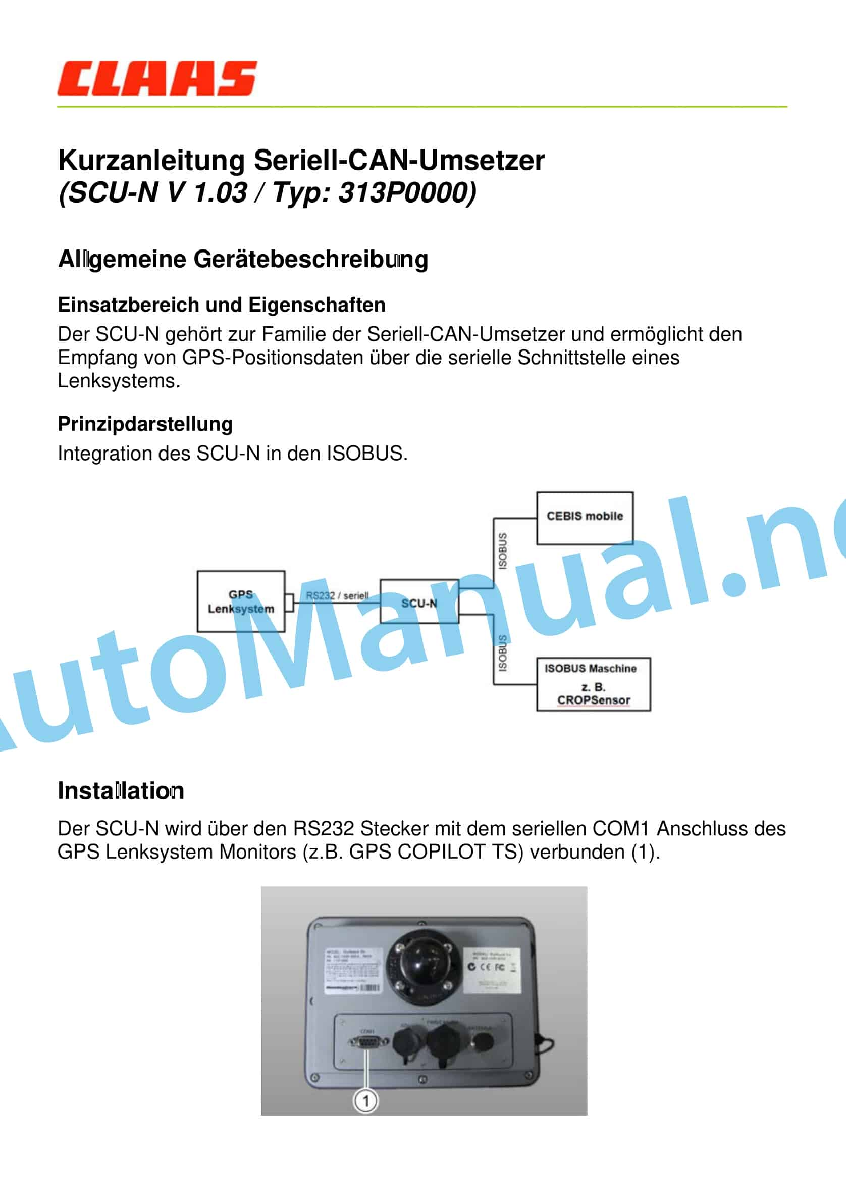
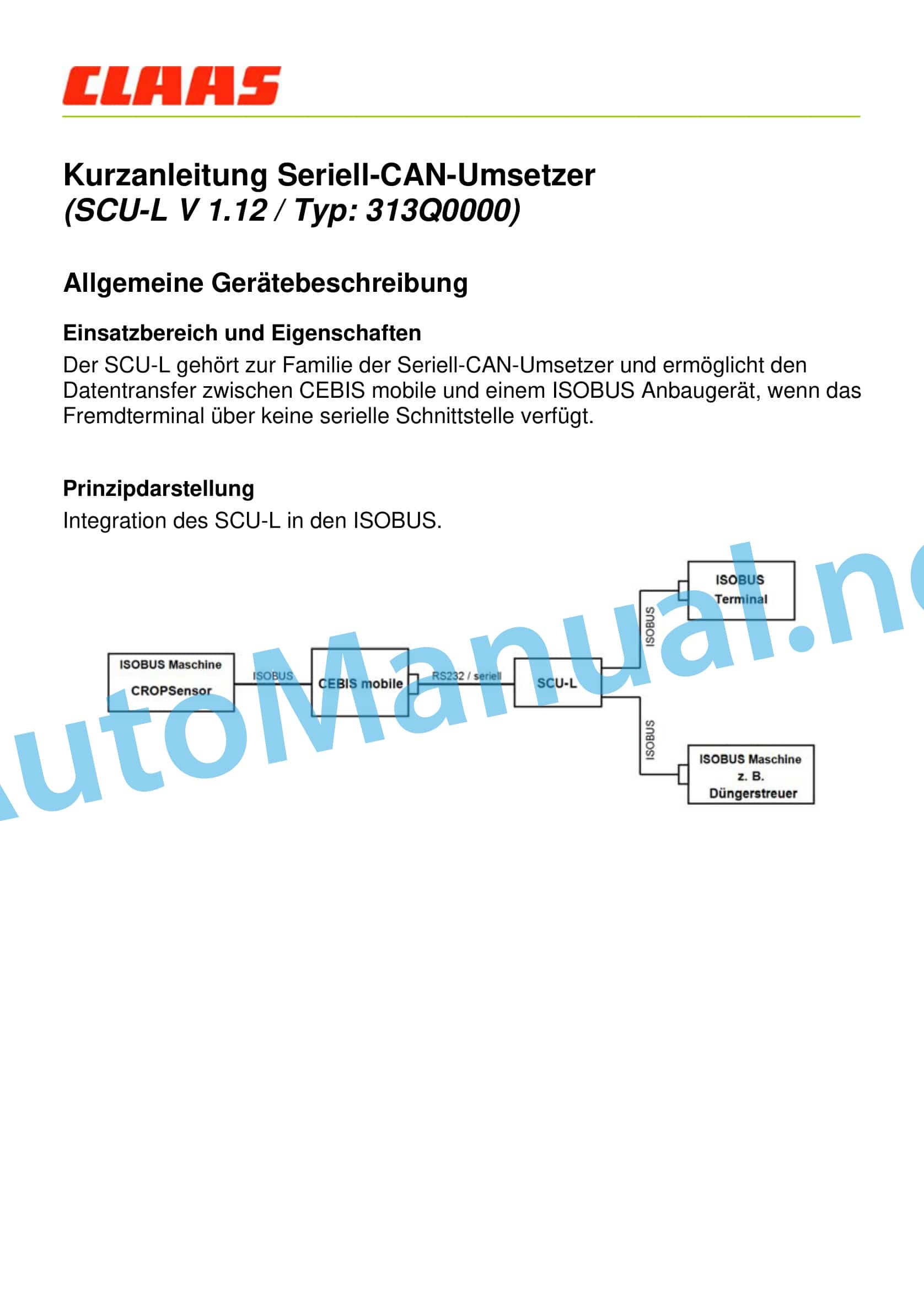
1 Short instructions for serial CAN converter (SCU-N V 1.03 / Type: 313P0000)
1.1 General device description
1.2 Installation
1.3 Settings
00 1400 632 2.pdf
Table of Content:
1 RTK FARM BASERTK FARM BASE LINKRTK FARM BASE Repeater
2 Table of Contents
3 1 Introduction
3.1 1.1 Notes on the instructions
3.2 1.2 Intended use
4 2 Security
4.1 2.1 Recognize warnings
4.2 2.2 Safety instructions
5 3 Product description
5.1 3.1 Overview and functionality RTK FARM BASE
5.2 3.2 Overview and functionality RTK FARM BASE LINK
5.3 3.3 Overview and functionnd display elements
6.1 4.1 Components
7 5 Technical data
7.1 5.1 RTK
7.2 5.2 Specification Components
8 6 Prepare product
8.1 6.1 Switch off and secure the product
8.2 6.2 Commissioning
8.3 6.3 Scope of delivery
8.4 6.4 Attachment RTK FARM BASE and RTK FARM BASE LINK
8.5 6.5 Attachment RTK FARM BASE Repeater
8.6 6.6 Connect components
8.7 6.7 Initial commissioning RTK FARM BASE and RTK FARM BASE LINK
8.8 6.8 Initial commissioning RTK FARM BASE Repeater
9 7 Operation
9.1 7.1 RTK FARM BASE, RTK FARM BASE LINK and RTK FARM BASE Repeater
10 8 Malfunction and remedy
10.1 8.1 RTK FARM BASE, RTK FARM BASE LINK and RTK FARM BASE Repeater
11 9 Maintenance
11.1 9.1 Overview of maintenance intervals
12 10 Decommissioning and disposal
12.1 10.1 General information
13 11 technical terms and abbreviations
13.1 11.1 Abbreviations
13.2 11.2 Units
00 1400 634 3.pdf
Table of Content:
1 GPS COPILOT S7
2 Table of Contents
3 1 Introduction
3.1 1.1 General information
3.2 1.2 Intended use
4 2 Security
4.1 2.1 Recognize warnings
4.2 2.2 Safety instructions
5 3 Product description
5.1 3.1 Overview and functionality
5.2 3.2 Optional equipment
5.3 3.3 Type plates and identification numbers
6 4 Control and display elements
6.1 4.1 Overview S7 Terminal
6.2 4.2 Menu structure GPS COPILOT
7 5 Technical data
7.1 5.1 GPS COPILOT
7.2 5.2 S7 Terminal
8 6 Prepare product
8.1 6.1 Switch off and secure the machine
8.2 6.2 Carry out before commissioning
8.3 6.3 Initial commissioning machine
8.4 6.4 Initial commissioning of the implement
8.5 6.5 Initial commissioning correction signal
8.6 6.6 Set subscriptions
9 7 Operation
9.1 7.1 Checklists
9.2 7.2 GPS COPILOT
9.3 7.3 GPS Settings
9.4 7.4 System Settings
9.5 7.5 Vehicle settings
9.6 7.6 Device settings
9.7 7.7 Order management
9.8 7.8 Field trip with GPS COPILOT
9.9 7.9 Boundaries and markers
9.10 7.10 Straight lines
9.11 7.11 Circular line guidance
9.12 7.12 Contour line guidance
9.13 7.13 Section display
10 8 Malfunction and remedy
10.1 8.1 Errors and measures
10.2 8.2 S7 Terminal
10.3 8.3 Diagnosis
11 9 Maintenance
11.1 9.1 Overview of maintenance intervals
12 10 Decommissioning and disposal
12.1 10.1 General information
13 11 EC declaration of conformity
13.1 11.1 GPS COPILOT
14 12 technical terms and abbreviations
14.1 12.1 GPS COPILOT
00 1400 859 2.pdf
Table of Content:
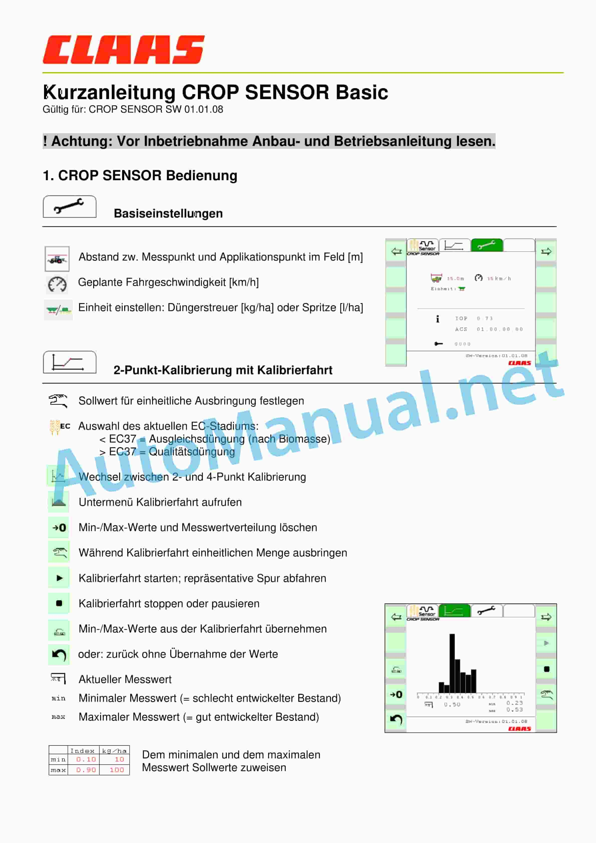
1 Quick guide CROP SENSOR Basic
1.1! Attention: Read the installation and operating instructions before commissioning.
1.2 1. CROP SENSOR Operation
2 Attention: If the application rate is limited by the min/max quantity, this is only possible on the work screen via the display
3 2. Status and error messages
00 1401 207 1.pdf
Table of Content:
1 CROP SENSOR
2 Table of Contents
3 1 Notes on the instructions
3.1 1.1 General information
4 2 Security
4.1 2.1 Safety instructions
4.2 2.2 Safety markings on the machine
5 3 Machine description
5.1 3.1 Machine overview
5.2 3.2 Type plates and identification number
6 4 Control and display elements
6.1 4.1 CEBIS MOBILE
6.2 4.2 Menu structure
7 5 Cultivation
7.1 5.1 Safety instructions
7.2 5.2 Scope of delivery
7.3 5.3 ISOBUS basic equipment
7.4 5.4 3-point adapter
7.5 5.5 CROP SENSOR
8 6 Technical data
8.1 6.1 CROP SENSOR
9 7 Prepare machine
9.1 7.1 Safety instructions
9.2 7.2 Checklists
9.3 7.3 CROP SENSOR
10 8 Operation
10.1 8.1 Safety instructions
10.2 8.2 Field operation
10.3 8.3 Transport
11 9 Maintenance
11.1 9.1 General maintenance instructions
11.2 9.2 Maintenance tables
11.3 9.3 Lubrication plan
11.4 9.4 CROP SENSOR
12 10 Service
12.1 10.1 General information
13 11 Decommissioning and disposal
13.1 11.1 General information
14 12 EC declaration of conformity
14.1 12.1 CROP SENSOR
15 13 technical terms and abbreviations
15.1 13.1 Terms and explanations
00 1401 208 4.pdf
Table of Content:
1 CEBIS MOBILE
2 Table of Contents
3 1 About these operating instructions
3.1 1.1 Notes on the instructions
4 2 Security
4.1 2.1 Intended use
4.2 2.2 Safety instructions
4.3 2.3 Safety instructions in these instructions
5 3 Product description
5.1 3.1 Overview and functionality
5.2 3.2 Optional equipment
5.3 3.3 Type plates and identification number
6 4 Control and display elements
6.1 4.1 On-board computer CEBIS MOBILE
6.2 4.2 Menu structure Universal Terminal (Service)
6.3 4.3 Menu structure order processing (task)
7 5 Technical data
7.1 5.1 CEBIS MOBILE
7.2 5.2 GPS source
7.3 5.3 Serial coupling
8 6 Cultivation
8.1 6.1 Scope of delivery
8.2 6.2 Mounting ISOBUS components
8.3 6.3 Mounting GPS source
9 7 Prepare product
9.1 7.1 Switch off and secure the machine
9.2 7.2 Carry out before commissioning
10 8 Operation
10.1 8.1 On-board computer CEBIS MOBILE
10.2 8.2 Switch CEBIS MOBILE on/off
10.3 8.3 Programmable buttons
10.4 8.4 ISOBUS settings
10.5 8.5 Terminal Settings
10.6 8.6 Error message Universal Terminal
10.7 8.7 ISOBUS order management
10.8 8.8 ISOBUS order management settings
10.9 8.9 GPS information
10.10 8.10 Error message order management
10.11 8.11 Driving on the road
11 9 Malfunction and remedy
11.1 9.1 Overview of faults
11.2 9.2 CEBIS MOBILE
12 10 Maintenance
12.1 10.1 Overview of maintenance intervals
12.2 10.2 CEBIS MOBILE
13 11 Decommissioning and disposal
13.1 11.1 General information
14 12 EC declaration of conformity
14.1 12.1 CEBIS MOBILE ISOBUS
15 13 technical terms and abbreviations
15.1 13.1 CEBIS MOBILE
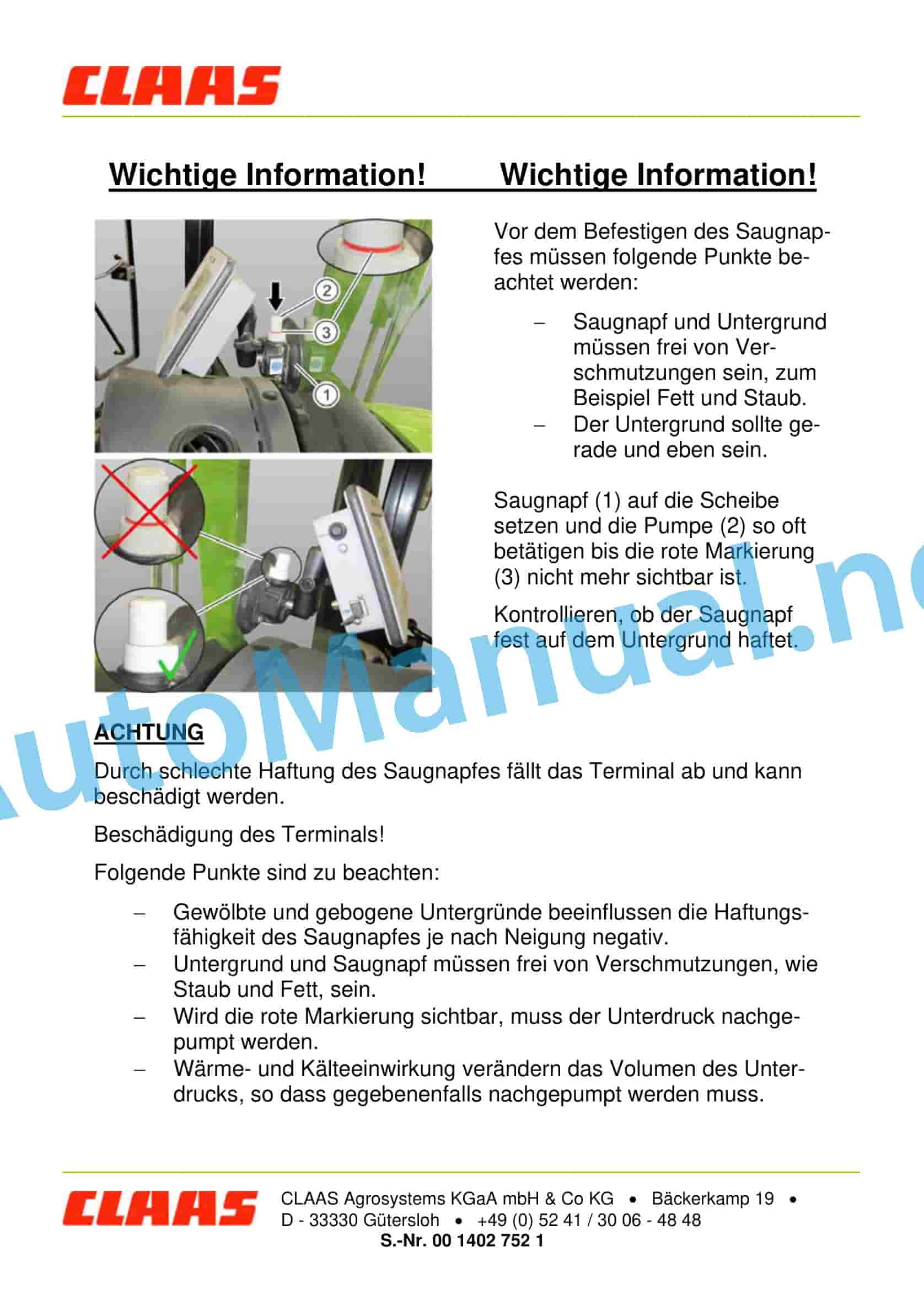
00 1402 752 1.pdf
Table of Content:
1 Important information! Important information!
1.1 ATTENTION
00 1405 858 1.pdf
Table of Content:
1 TELEMATICS
2 Table of Contents
3 1 About these operating instructions
3.1 1.1 Notes on the instructions
4 2 Security
4.1 2.1 Intended use
4.2 2.2 Safety instructions
5 3 Product description
5.1 3.1 Overview and functionality
5.2 3.2 Type plates and identification numbers
6 4 Control and display elements
6.1 4.1 Module
7 5 Technical data
7.1 5.1 Module
7.2 5.2 Antennas
8 6 Prepare product
8.1 6.1 Switch off and secure the machine
8.2 6.2 Prepare memory card
8.3 6.3 EU-28 countries
8.4 6.4 EU-28 countries with external SIM card / Non-EU-28 countries
8.5 6.5 Prepare machine
8.6 6.6 Automatic activation of the machine
9 7 Operation
9.1 7.1 Using TELEMATICS
10 8 Malfunction and remedy
10.1 8.1 Overview of faults
11 9 Decommissioning and disposal
11.1 9.1 General information
12 10 technical terms and abbreviations
12.1 10.1 Technical terms and abbreviations
00 1420 000 2.pdf
Table of Content:
1 Fleet View App
2 Table of Contents
3 1 Introduction
3.1 1.1 Notes on the instructions
3.2 1.2 Intended use
3.3 1.3 Software update
3.4 1.4 Malfunction and remedy
3.5 1.5 Technical terms and abbreviations
4 2 Security
4.1 2.1 Recognize warnings
4.2 2.2 Safety instructions
5 3 Technical data
5.1 3.1 Technical requirements
5.2 3.2 Data update
6 4 Control and display elements
6.1 4.1 Overview Fleet View App
6.2 4.2 Overview of function bar
6.3 4.3 Functions of the Fleet View App
6.4 4.4 Operating the keyboard
7 5 Start app
7.1 5.1 Activate Fleet View App
7.2 5.2 Select machine
8 6 Operation
8.1 6.1 Fleet View Map
8.2 6.2 Machine list
8.3 6.3 Change machine
8.4 6.4 Log out user
8.5 6.5 Close app
9 7 Working Groups
9.1 7.1 Working Groups
9.2 7.2 Select workgroup
9.3 7.3 Create workgroup
9.4 7.4 Add your own machines
9.5 7.5 Add external machines
9.6 7.6 Edit workgroups
9.7 7.7 Delete workgroup
10 8 Settings
10.1 8.1 Settings
11.1 9.1 Where can I find the version number?
11.2 9.2 Why are machines not displayed?
11.3 9.3 How are tablet licenses allocated?
00 1420 320 0.pdf
Table of Content:
1 Fleet View App
2 Table of Contents
3 1 Introduction
3.1 1.1 Notes on the instructions
3.2 1.2 Intended use
3.3 1.3 Software update
3.4 1.4 Malfunction and remedy
3.5 1.5 Technical terms and abbreviations
4 2 Security
4.1 2.1 Recognize warnings
4.2 2.2 Safety instructions
5 3 Technical data
5.1 3.1 Technical requirements
5.2 3.2 Data update
6 4 Control and display elements
6.1 4.1 Main menu
6.2 4.2 Functions of the Fleet View App
6.3 4.3 Operating the keyboard
7 5 Start app
7.1 5.1 Activate Fleet View App
7.2 5.2 Select machine
8 6 Operation
8.1 6.1 Fleet View Map
8.2 6.2 Machine list
8.3 6.3 Change machine
8.4 6.4 Log out user
8.5 6.5 Close app
9 7 Working Groups
9.1 7.1 Working Groups
9.2 7.2 Select workgroup
9.3 7.3 Create workgroup
9.4 7.4 Add your own machines
9.5 7.5 External machine
New Holland Service Manual PDF
John Deere Repair Technical Manual PDF
John Deere 16, 18, 20 and 24HP Onan Engines Component Technical Manual CTM2 (19APR90)
John Deere Repair Technical Manual PDF
John Deere Repair Technical Manual PDF
John Deere Parts Catalog PDF
John Deere Tractors 7500 Parts Catalog CPCQ26568 30 Jan 02 Portuguese
John Deere Repair Technical Manual PDF
John Deere Repair Technical Manual PDF
John Deere Repair Technical Manual PDF
John Deere Diesel Engines POWERTECH 2.9 L Component Technical Manual CTM126 Spanish
John Deere Repair Technical Manual PDF
John Deere Repair Technical Manual PDF

