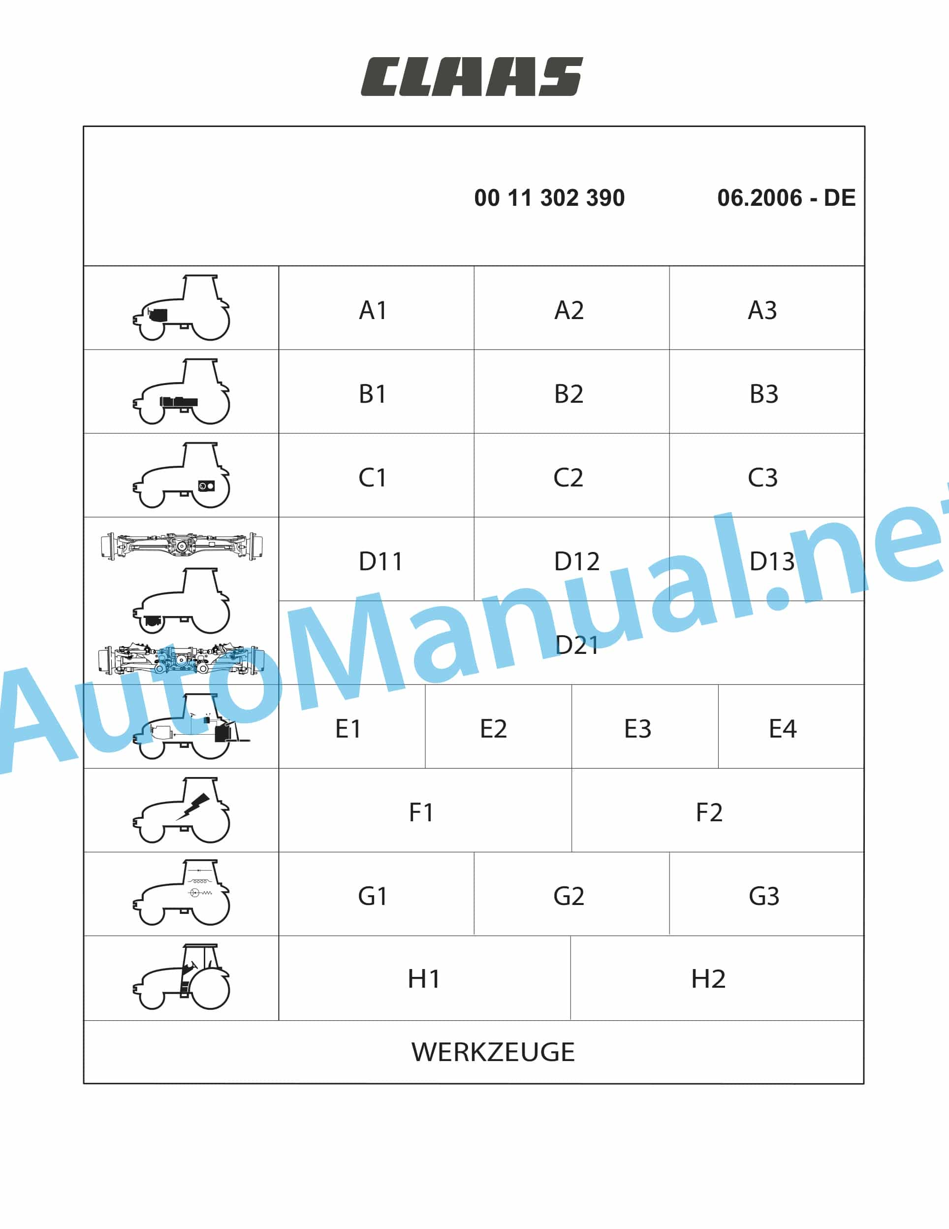
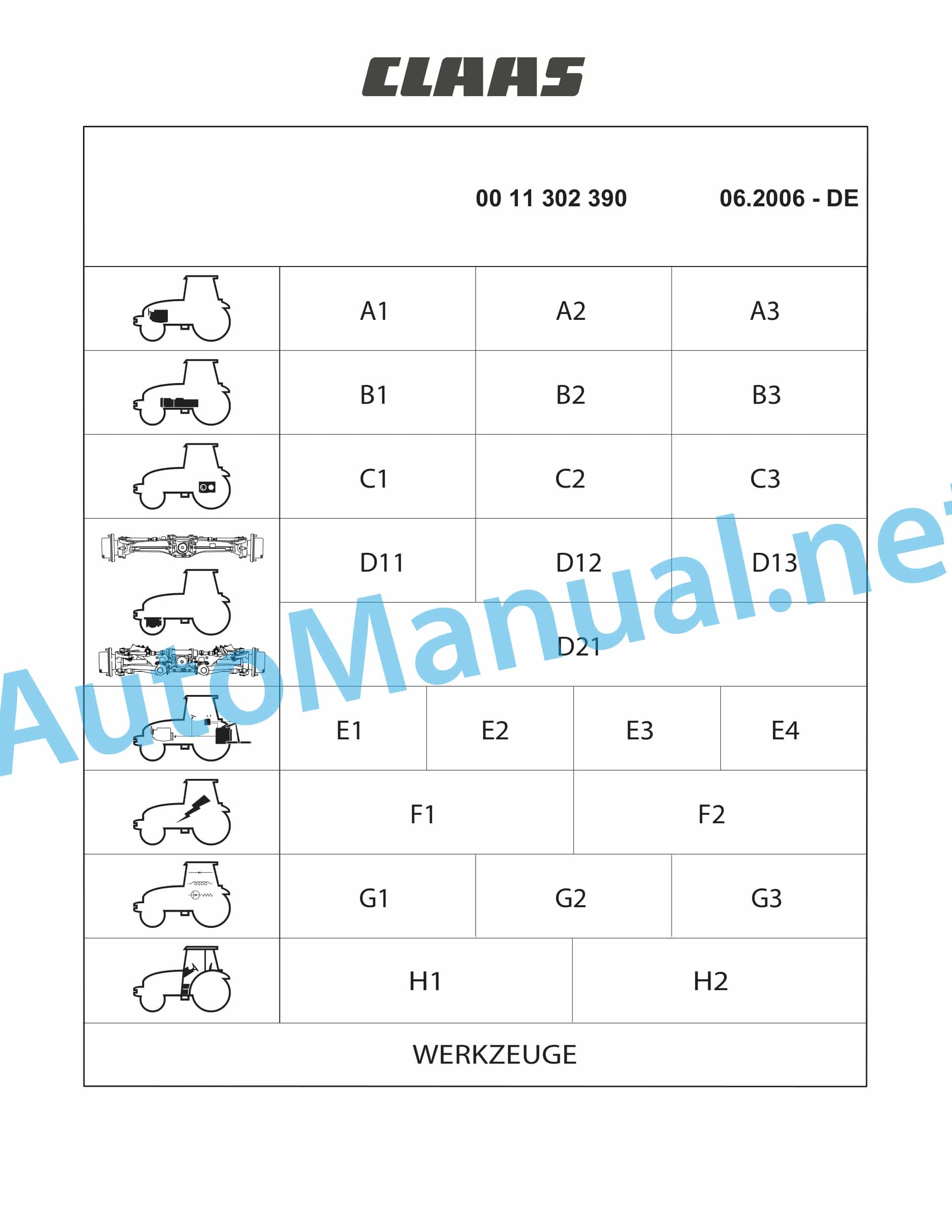
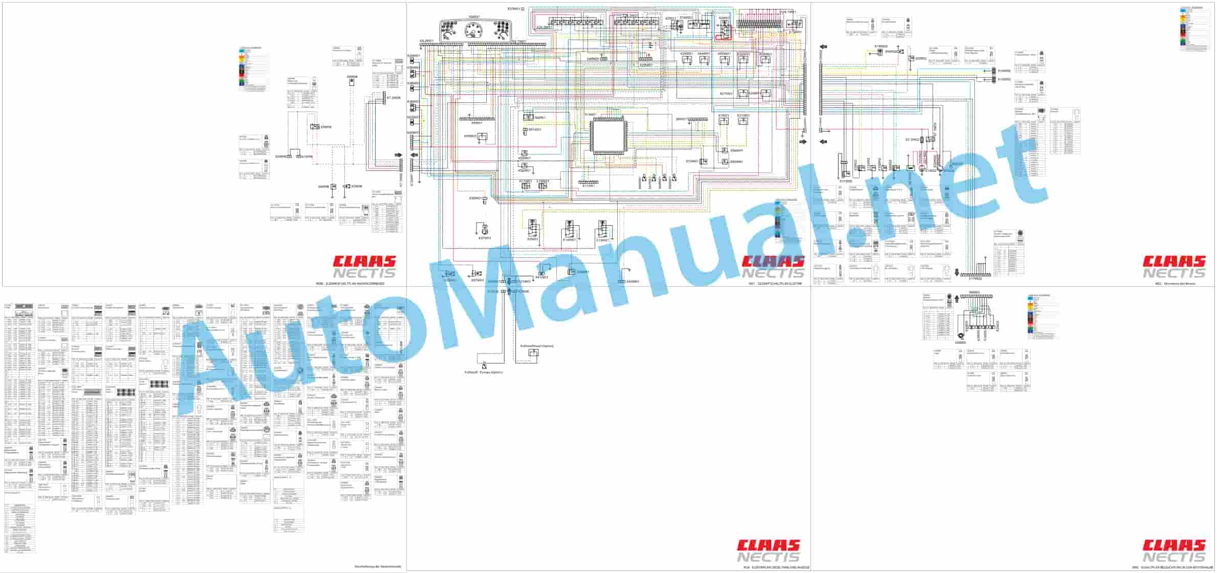
Claas NECTIS VE 237 227 217 2+4WD (T14) Tractor Repair Manual DE
$300.00
- Model: NECTIS VE 237 227 217 2+4WD (T14) Tractor
- Type Of Manual: Repair Manual
- Language: DE
- Format: PDF(s)
- Size: 169 MB
File List:
– 00 1130 239 0.pdf
– Contents.pdf
– Chapter A – Overview.pdf
– Chapter A1 – CONTROL PROCEDURES INJECTION DATA SHEETS.pdf
– Chapter A2 – SUPPLY OF INJECTION.pdf
– Chapter A3 – ENGINE IVECO.pdf
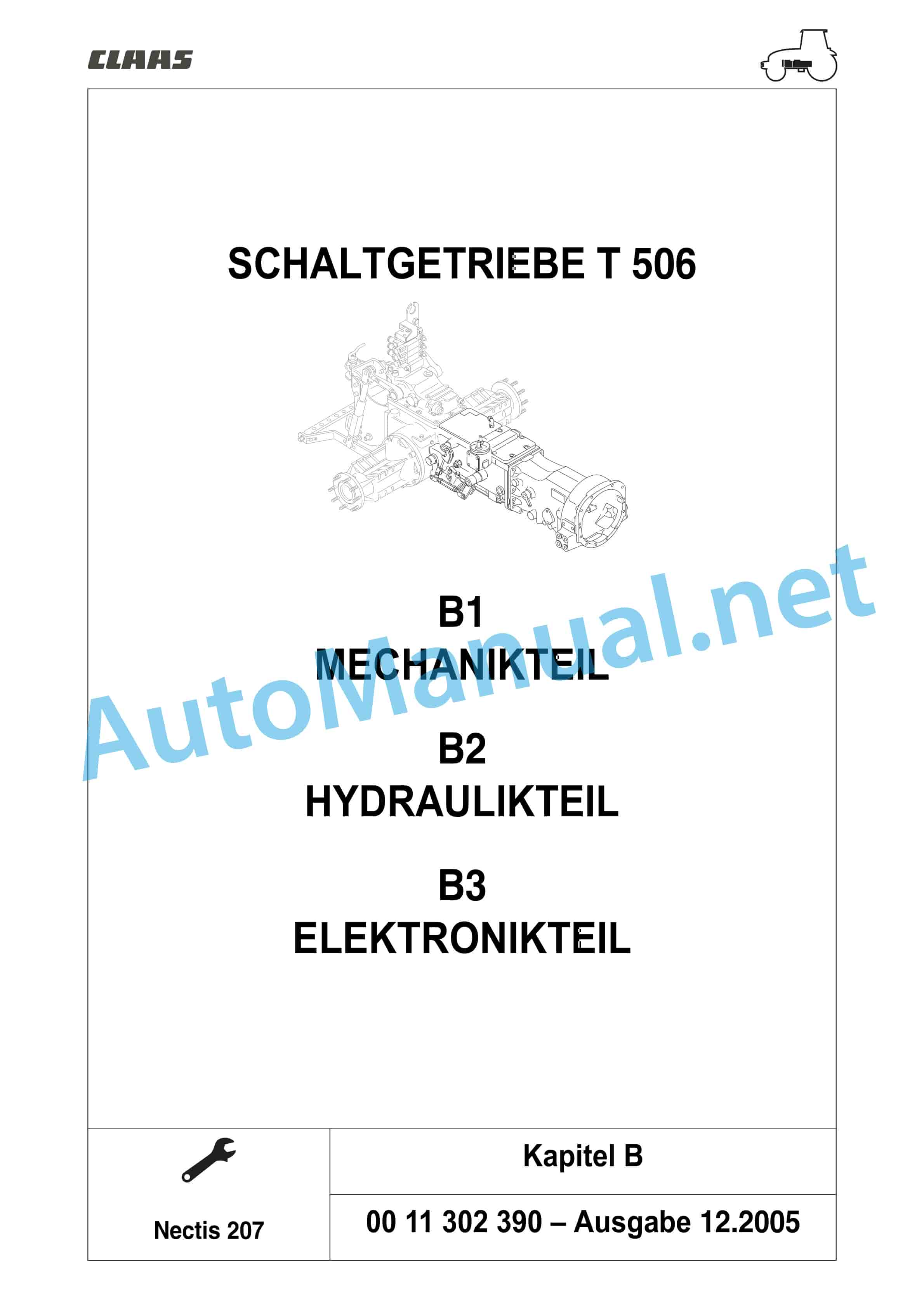
– Chapter B – Overview.pdf
– Chapter B1 – MECHANICAL PART.pdf
– Chapter B2 – HYDRAULIC PART.pdf
– Chapter B3 – ELECTRONIC PART.pdf
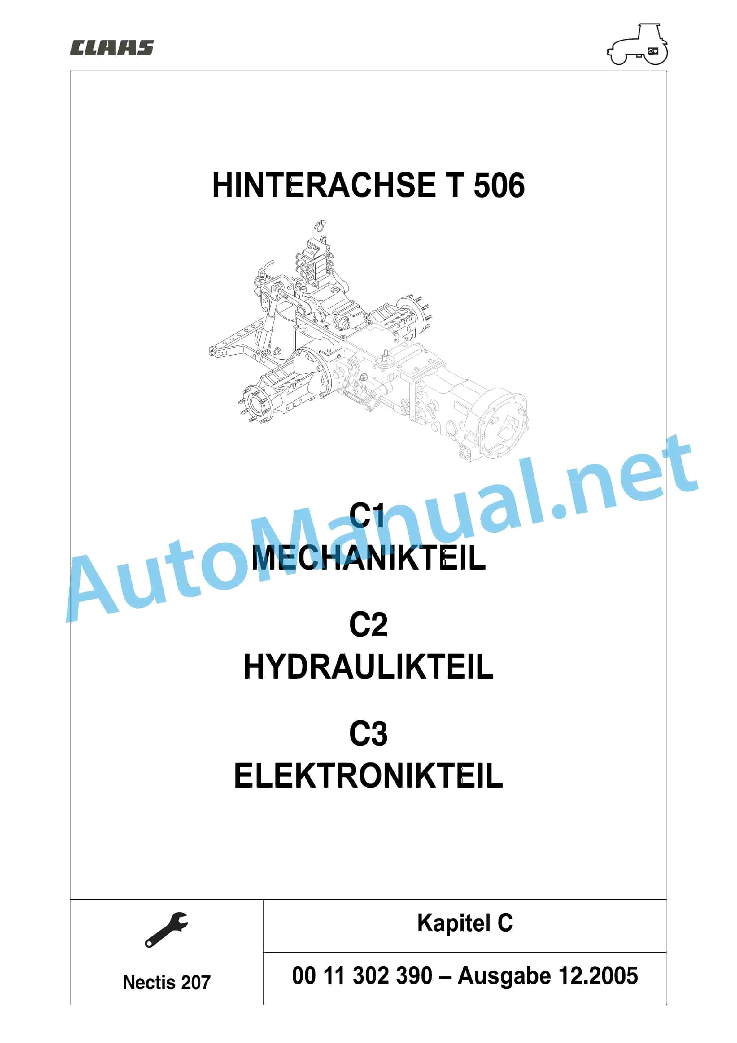
– Chapter C – Overview.pdf
– Chapter C1 – MECHANICAL PART.pdf
– Chapter C2 – HYDRAULIC PART.pdf
– Chapter C3 – ELECTRONIC PART.pdf
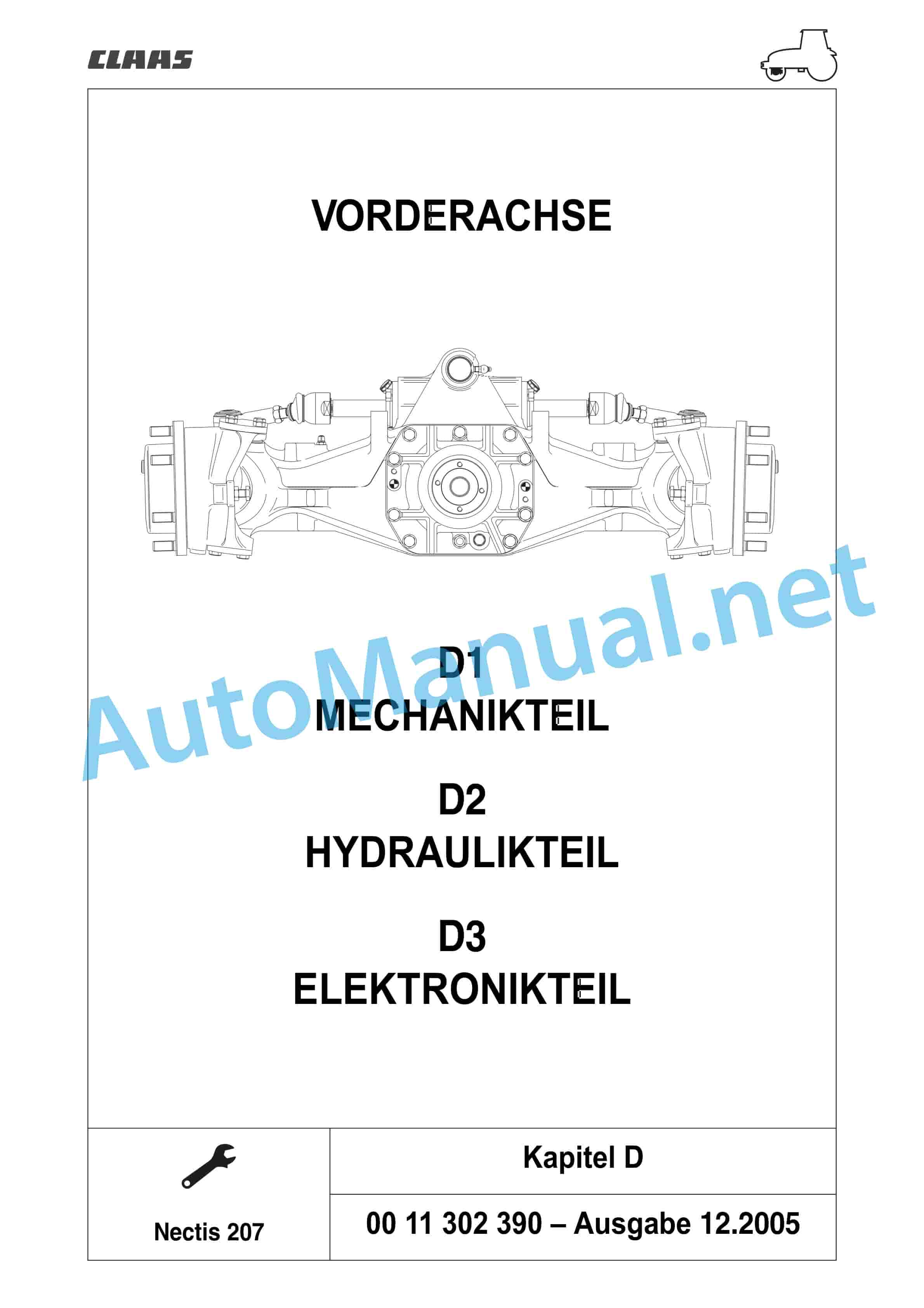
– Chapter D10 – FRONT AXLE, MECHANICAL PART, HYDRAULIC PART, ELECTRONIC PART.pdf
– Chapter D11 – MECHANICAL PART.pdf
– Chapter D12 – HYDRAULIC PART.pdf
– Chapter D13 – ELECTRONIC PART.pdf
– Chapter D20 – FRONT AXLE MECHANICAL PART.pdf
– Chapter D21 – MECHANICAL PART.pdf
– Chapter E – Overview.pdf
– Chapter E1 – COMMON COMPONENTS.pdf
– Chapter E2 – CIRCUIT WITH 1 PUMP.pdf
– Chapter E3 – CIRCUIT WITH 2 PUMPS.pdf
– Chapter E4 – CIRCUIT WITH 3 PUMPS.pdf
– Chapter F – Overview.pdf
– Chapter F1 – CIRCUIT SCHEMATA.pdf
– Chapter F2 – CABLE HARNESSES AND CONNECTORS.pdf
– Chapter G – Overview.pdf
– Chapter G1 – DASHBOARD.pdf
– Chapter G2 – ELECTRONIC HITCH TCE 6.pdf
– Chapter G3 – USER MANUAL WIN MTADIAG.pdf
– Chapter H – Overview.pdf
– Chapter H1 – RAISING THE DRIVER CAB AND PLATFORM.pdf
– Chapter H2 – HEATING AIR CONDITIONING.pdf
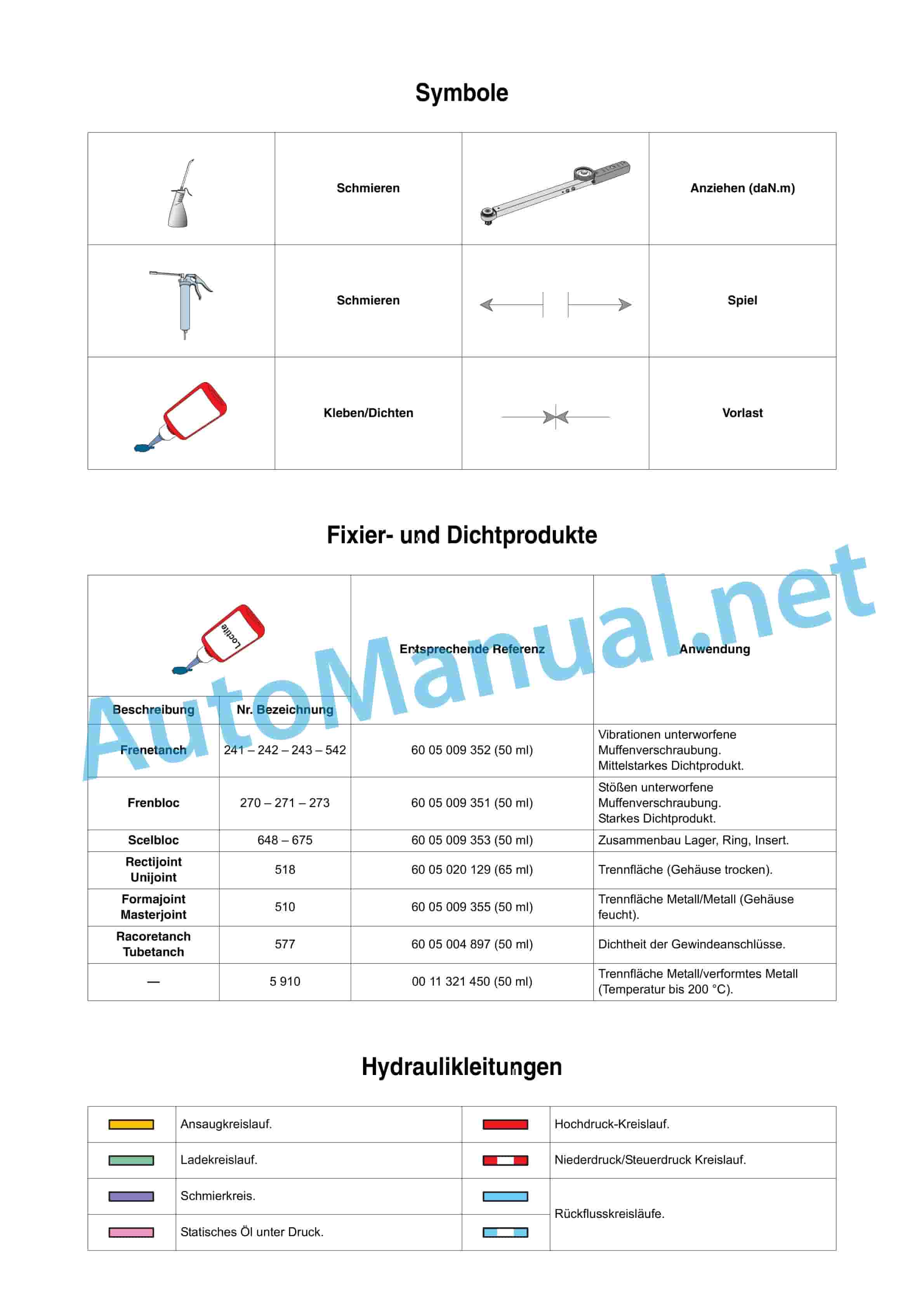
– Chapter symbols, fixing and sealing products, hydraulic lines, standardized tightening torques.pdf
– Nectic Trax.pdf
00 1130 239 0.pdf
Table of Content:
2 A1 CONTROL PROCEDURES INJECTION DATA SHEETS
3 A2 SUPPLY OF INJECTION
4 A3 ENGINE IVES
21 G1 – DASHBOARD
22 G2 – ELECTRONIC HITCH TCE 6
23 G3 – USER MANUAL WIN MTADIAG
24 H1 – RAISE DRIVER CAB AND PLATFORM
25 H2 – HEATING/AIR CONDITIONING
Contents.pdf
Table of Content:
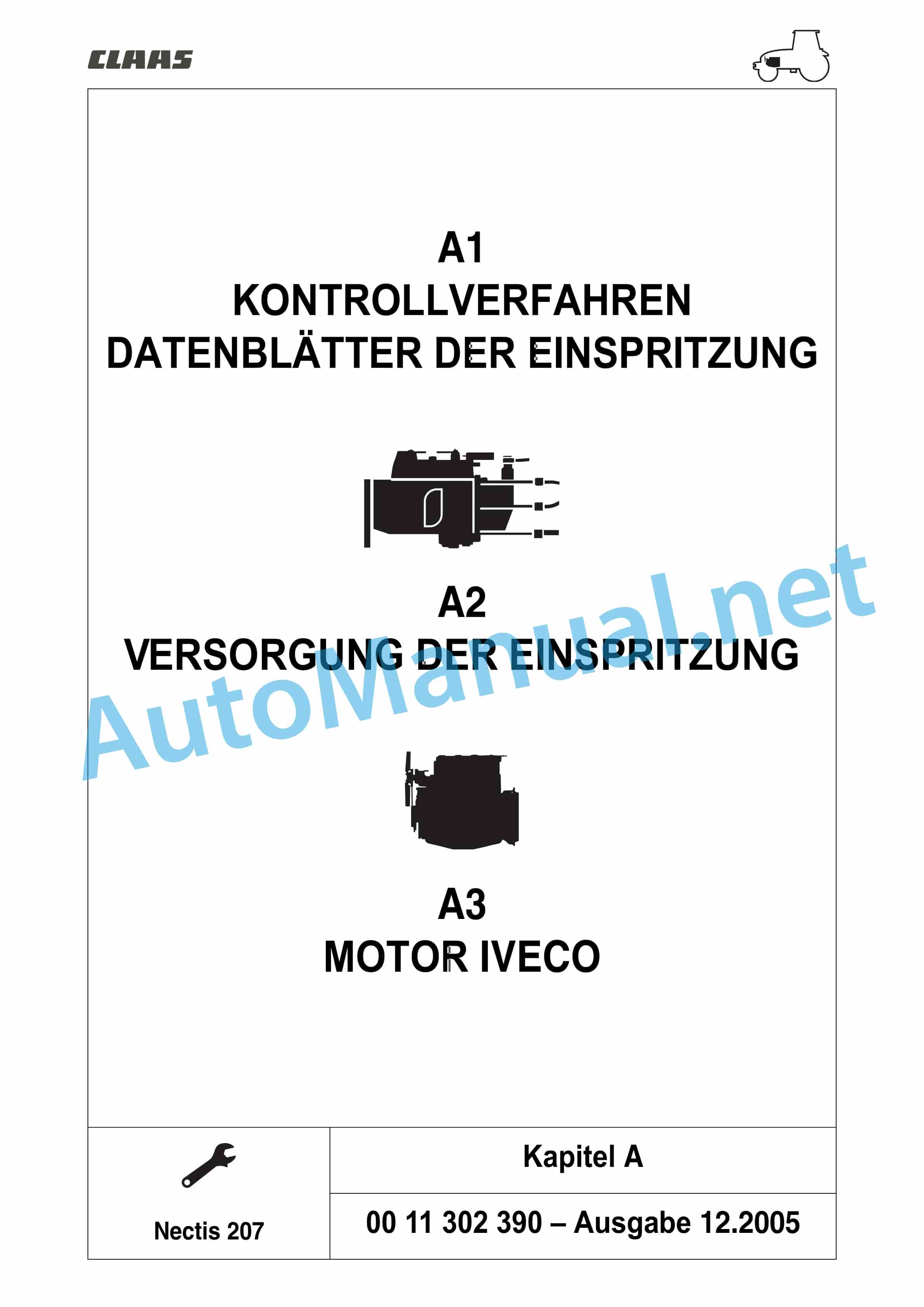
2 A1 CONTROL PROCEDURES INJECTION DATA SHEETS
3 A2 SUPPLY OF INJECTION
4 A3 ENGINE IVECO
5 B1 MECHANICAL PART
6 B2 HYDRAULIC PART
7 B3 E INJECTION DATA SHEETS
2 A2 SUPPLY OF INJECTION
3 A3 ENGINE IVECO
4 CONTENTS NECTIS 207
Chapter A1 – CONTROL PROCEDURES INJECTION DATA SHEETS.pdf
Table of Content:
1 A1 CONTROL PROCEDURES INJECTION DATA SHEETS
1.1 Control procedures
1.2 Measuring and control points
1.3 INJECTION DATA SHEET
2 CONTENTS NECTIS 207
Chapter A2 – SUPPLY OF INJECTION.pdf
Table of Content:
1 A2 SUPPLY OF INJECTION
1.1 Identifier
1.2 Tightening torques
1.3 Description
1.4 Controls and Settings
1.5 Removal/reinstallation
1.6 Diagnosis
2 CONTENTS NECTIS 207
ChIC PART
3 B3 ELECTRONIC PART
4 CONTENTS NECTIS 207
Chapter B1 – MECHANICAL PART.pdf
Table of Content:
1 B1 MECHANICAL PART
1.1 General Specifications
1.2 Expansion
1.3 Tightening torque and main settings
1.4 Tightening torques and sealing products
1.5 Transmission with mechanical clutch
1.6 Gearbox with shuttle and hydraulic doubler
1.7 Gearbox
2 CONTENTS NECTIS 207
Chapter B2 – HYDRAULIC PART.pdf
Table of Content:
1 B2 HYDRAULIC PART
1.1 Hydraulic “Control values”
2 CONTENTS NECTIS 207
Chapter B3 – ELECTRONIC PART.pdf
Table of Content:
1 B3 ELECTRONIC PART
1.1 Electronic transmission control
1.2 Arrangement of compone”Control values”
2 CONTENTS NECTIS 207
Chapter C – Overview.pdf
Table of Content:
1 C1 MECHANICAL PART
2 C2 HYDRAULIC PART
3 C3 ELECTRONIC PART
4 CONTENTS NECTIS 207
Chapter C1 – MECHANICAL PART.pdf
Table of Content:
1 C1 MECHANICAL PART
1.1 Tightening torque and main settings
1.2 Drive bevel gear
1.3 Differential
1.4 Rear axle funnel
1.5 PTO shaft
“Control values”
2 CONTENTS NECTIS 207
Chapter C3 – ELECTRONIC PART.pdf
Table of Content:
1 C3 – ELECTRONIC PART
1.1 Electronic control of the rear axle
1.2 Arrangement of components
1.3 Electrical tests
1.4 Measuring and control points
1.5 sheet “Control values”
2 CONTENTS NECTIS 207
Chapter D10 – FRONT AXLE, MECHANICAL PART, HYDRAULIC PART, ELECTRONIC PART.pdf
Table of Content:
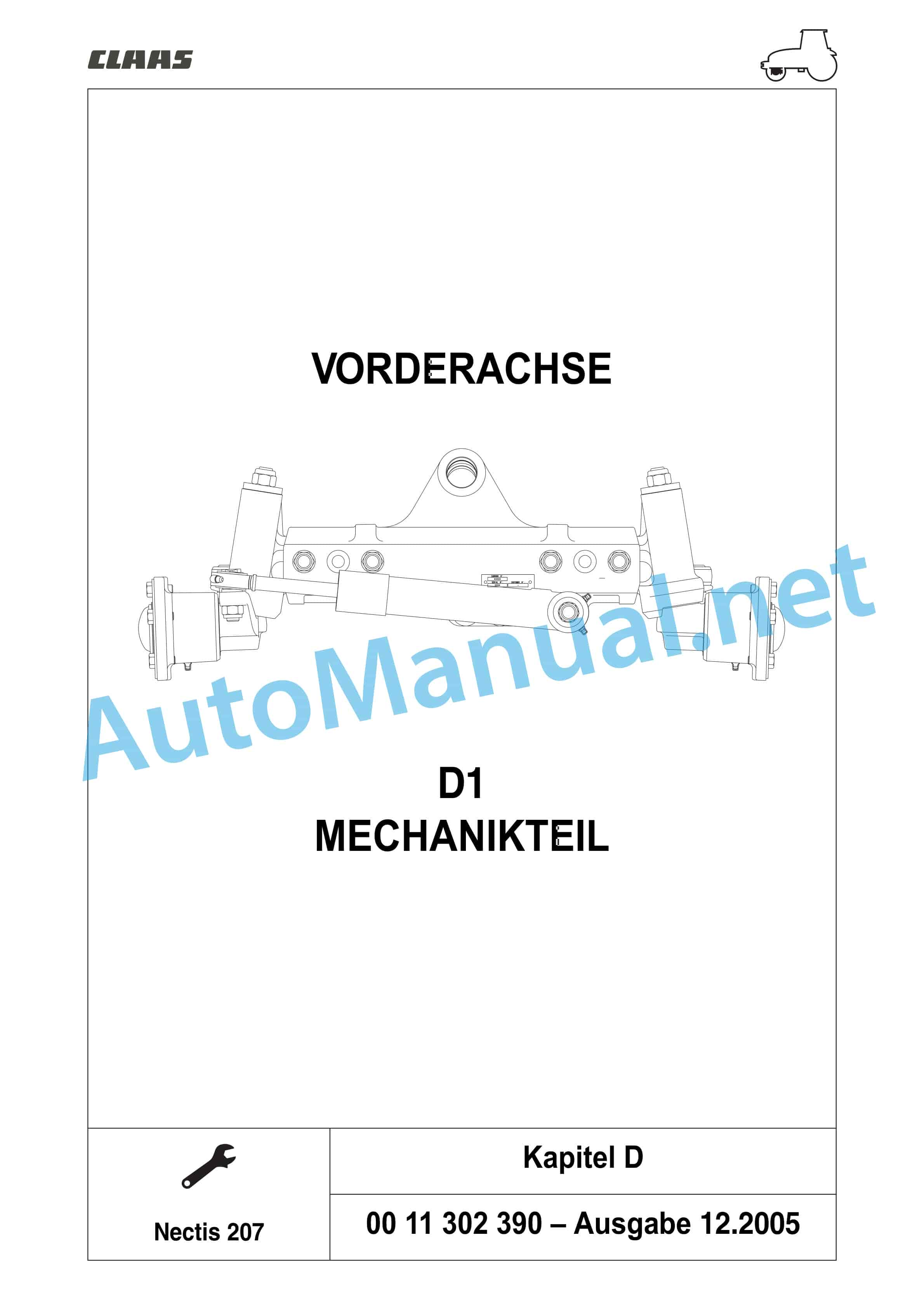
1 FRONT AXLE D1 MECHANICAL PART
2 FRONT AXLE D2 HYDRAULIC PART
3 FRONT AXLE D3 ELECTRONIC PART
4 CONTENTS NECTIS 207
Chapter D11 – MECHANICAL PART.pdf
Table of Content:
1 D1 – MECHANICAL PART
1.1 General
1.2 Tightening torques and sealing products
1.3 Pa”20.09 C”
1.9 Reduction gear and wheel hub of axles “20.09” and “20.11”
1.10 Wheel bolts and wheel hub carrier
1.11 Bevel gear and differential
1.12 4-wheel transmission with electro-hydraulic engagement
1.13 4-wheel transmission with mechanical activation
2 CONTENTS NECTIS 207
Chapter D12 – HYDRAULIC PART.pdf
Table of Content:
1 D2 – HYDRAULIC PART
1.1 Hydraulic system
1.2 Engaging the front axle
1.3 Measuring and control points
1.4 Sheet “Control values”
2 CONTENTS NECTIS 207
Chapter D13 – ELECTRONIC PART.pdf
Table of Content:
1 D3 – ELECTRONIC PART
1.1 Electronic control of the front axle
1.2 Arrangement of components
1.3 Electrical tests
1.4 Measuring and control points
1.5 sheet “Control values”
2 CONTENTS NECTIS 207
Chapter D20 – FRONT AXLE MECHANICAL PART.pdf
Table of Content:
1 FRONT AXLE D1 MECHANICAL PART
2 CONTENTS NECTIS 207
Chapter D21 – MECHANICAL PART.pdf
Table of Content:
1 D1 – MECHANICAL PART
1.1 General
1.2 Tightening torques
1.3 Parallelism
1.4 Removing/reinstalling the front axle
1.5 Steering cylinder
1.6 Steering knuckle carrier
1.7 Wheel hub
2 CONTENTS NECTIS 207
Chapter E – Overview.pdf
Table of Content:
1 E1 COMMON COMPONENTS
2 E2 CIRCUIT WITH 1 PUMP
3 E3 CIRCUIT WITH 2 PUMP
4 E4 CIRCUIT WITH 3 PUMP
5 draulic lifting rod
1.10 Mechanical power lift control valve
1.11 Electronic power lift TCE 6
1.12 Power lift housing
2 CONTENTS NECTIS 207
Chapter E2 – CIRCUIT WITH 1 PUMP.pdf
Table of Content:
1 E2 – CIRCUIT WITH 1 PUMP
1.1 Overview
1.2 Arrangement of components
1.3 Hydraulic measuring and control points
1.4 Data sheet “Determination of control values” for hydraulics
1.5 Hydraulic measuring and control points
1.6 Data sheet “Determination of control values” for hydraulics
2 CONTENTS NECTIS 207
Chapter E3 – CIRCUIT WITH 2 PUMP.pdf
Table of Content:
1 E3 – CIRCUIT WITH 2 PUMP
1.1 Overview
1.2 Arrangement of components
1.3 Hydraulic measuring and control points
1.4 Data sheet “Determination of control values” for hydraulics
1.5 Hydraulic measuring and control points
1.6 Data sheet “Determination of control values” for hydraulics
2 CONTENTS NECTIS 207
Chapter E4 – CIRCUIT WITH 3 PUMPS.pdf
Table of Content:
1 E4 – CIRCUIT WITH 3 PUMP
1.1 Overview
1.2 Arrangement of components
1.3 Hydraulic measuring and control points
1.4 Data sheet “Determination of control values” for hydraulics
1.5 Hydraulic measuring and control points
1.6 Data sheet “Determination of control values” for hydraulics
2 CONTENTS NECTIS 207
Chapter F – Overview.pdf
Table of Content:
1 F1 WIRING SCHEMATA
2 F2 CABLE HARNESSES AND CONNECTORS
3 CONTENTS NECTIS 207
Chapter F1 – CIRCUIT SCHEMATA.pdf
Table of Content:
1 F1 – CIRCUIT SCHEMATA
1.1 List of components
1.2 General wiring
1.3 Fuses and relays
1.4 Fuses and relays Revershift gearbox version
1.5 Fuses and relays version mechanical transmission
1.6 Fuse (b) and relay box cabin
1.8 Functions
2 CONTENTS NECTIS 207
Chapter F2 – CABLE HARNESSES AND CONNECTORS.pdf
Table of Content:
1 F2 – CABLE HARNESSES AND CONNECTORS
1.1 Cable sets and plugs
1.2 1. Cable set dashboard and gearbox
1.3 2nd cable set for preheating control (optional)
1.4 3. Radiator hood cable set
1.5 4. Motor cable set
1.6 4ar conditioning cable set
1.10 6. Cable set TCE6
2 CONTENTS NECTIS 207
Chapter G – Overview.pdf
Table of Content:
1 G1 DASHBOARD
2 G2 ELECTRONIC HITCH TCE 6
3 G3 USER MANUAL WIN MTADIAG
4 CONTENTS NECTIS 207
Chapter G1 – DASHBOARD.pdf
Table of Content:
1 G1 – DASHBOARD
1.1 Description
1.2 Technical data
1.3 Removal/reinstallation
1.4 Measuring and control points
2 CONTENTS NECTIS 207
Chapter G2 – ELECTRONIC POWER LIFT TCE 6.pdf
Table of Content:
1 G2 – ELECTRONIC HITCH TCE 6
1.1 Description
1.2 Settings
1.3 Measuring and control points
1.4 Data sheet with the control values a.pdf
Table of Content:
1 H1 RAISE THE DRIVER CAB AND PLATFORM
2 H2 HEATING/AIR CONDITIONING
3 CONTENTS NECTIS 207
Chapter H1 – RAISING THE DRIVER CAB AND PLATFORM.pdf
Table of Content:
1 H1 – RAISE DRIVER CAB AND PLATFORM
1.1 Description of the driver’s cabin
1.2 Removing the driver’s cab
1.3 Reinstalling the driver’s cab
1.4 Removal/reinstallation of the cabin roof
1.5 Description of the platform
1.6 Expansion of the platform
1.7 Replacing the platform
2 CONTENTS NECTIS 207
Chapter H2 – HEATING AIR CONDITIONING.pdf
Table of Content:
1 H2 – HEATING/AIR CONDITIONING
1.1 Technical data
1.2 General description
1.3 Description and functionality
1.4 Safety instructions
1.5 Draining and admitting gas
1.6 Removal/reinstallation
1.7 Measuring and control points
2 CONTENTS NECTIS 207
Nectic Trax.pdf
Table of Content:
1 Electrical scheme NECTIS TRAX
2 ELECTRICITE PRINCIPAL
3 DETAILS OF THE CONNECTOR
4 ELECTRICITE CAPOT MOTEUR(ECLAIRAGE)
5 ELECTRICITE MOTEUR
6 FREINAGE REMORQUE
7 RESERVOIR AUXILIAIRE
John Deere Repair Technical Manual PDF
John Deere Repair Technical Manual PDF
John Deere Repair Technical Manual PDF
John Deere Diesel Engines POWERTECH 2.9 L Component Technical Manual CTM126 Spanish
John Deere Repair Technical Manual PDF
John Deere Transmission Control Unit Component Technical Manual CTM157 15JUL05
John Deere Repair Technical Manual PDF
John Deere DF Series 150 and 250 Transmissions (ANALOG) Component Technical Manual CTM147 05JUN98
John Deere Parts Catalog PDF
John Deere Harvesters 8500 and 8700 Parts Catalog CPCQ24910 Spanish
John Deere Repair Technical Manual PDF
John Deere Repair Technical Manual PDF
John Deere PowerTech M 10.5 L and 12.5 L Diesel Engines COMPONENT TECHNICAL MANUAL CTM100 10MAY11
John Deere Parts Catalog PDF
John Deere Tractors 7500 Parts Catalog CPCQ26568 30 Jan 02 Portuguese
John Deere Repair Technical Manual PDF
John Deere POWERTECH E 4.5 and 6.8 L Diesel Engines TECHNICAL MANUAL 25JAN08

