Claas NEXOS VE 230-210 (A25) Tractor Repair Manual DE
$300.00
- Model: NEXOS VE 230-210 (A25) Tractor
- Type Of Manual: Repair Manual
- Language: DE
- Format: PDF(s)
- Size: 207 MB
File List:
– 00 1160 991 X.pdf
– Size(0.1 MB) 11/11/2011.pdf
– Size(0.6 MB) 6.27.2011.pdf
– Size(1 MB) 6.27.2011.pdf
– Size(11.3 MB) 10.5.2010.pdf
– Size(12 MB) 6.27.2011.pdf
– Size(2 MB) 6.27.2011.pdf
– Size(2.8 MB) 6.27.2011.pdf
– Size(32.2 MB) 6.24.2011.pdf
– Size(4.1 MB) 6.27.2011.pdf
– Size(50.5 MB) 9.6.2022.pdf
– Size(70.3 MB) 6.27.2011.pdf
– Sizeic0 lubricating oil system
6.7 0135 cooling system
6.8 0140 exhaust system
6.9 0145 air intake
6.10 0150 engine attachments
6.11 0155 Motor control
7 01 Motor
7.1 0102 Complete component
7.2 0110 Motor housing
7.3 0115 Motor Engine
7.4 0120 cylinder head / valves / distributor wheel
7.5 0125 Injection / Fuel System
7.6 0130 lubricating oil system
7.7 0135 cooling system
7.8 0140 exhaust system
7.9 0145 air intake
7.10 0150 engine attachments
7.11 0155 Motor control
8 02 Gearbox / clutch / cardan shaft
8.1 0202 Complete component
8.2 0215 Mechanical clutch
8.3 0218 Control / actuation clutch
8.4 0220 Mechanical reversing
8.5 0222 Hydraulic reversing
8.6 0230 Mechanical gears
8.7 0234 powershift transmission
8.8 0238 Control / actuation gearbox
8.9 0240 rear axle housing
8.10 0242 Differential
8.11 0248 Control / actuation rear axle
8.12 0250 Mechanical front axle drive
8.13 0252 Electro-hydraulic front axle drive
8.14 0255 Gearbox cooling system
8.15 0260 PTO shaft
9 03 Chassis
9.1 0310 Axis
9.2 0320 Steering axle
9.3 0325 Front steering drive axle
9.4 0340 front wheels
10 04 Brake
10.1 0405 Service brake
10.2 0415 parking brake
11 06 Lifting device
11.1 0605 rear power lift
11.2 0610 Front power lift
11.3 0615 Front loader
12 08 Drives
12.1 0802 Rear PTO
12.2 0804 Front PTO
13 09 Hydraulics
13.1 0910 Pumps
13.2 0920 Valves
14 12 Cab / Driver’s cab
14.1 1210 Cabin
14.2 1215 Driver’s cab
14.3 1240 Air conditioning
15 80 attachments, machine housing
15.1 8025 fairings / hoods
15.2 8035 Ballast / additional weight
Sizect:
1 CLAAS NECTIS
1.1 Mechanical clutch: New adjustment procedure for the play of the driving clutch
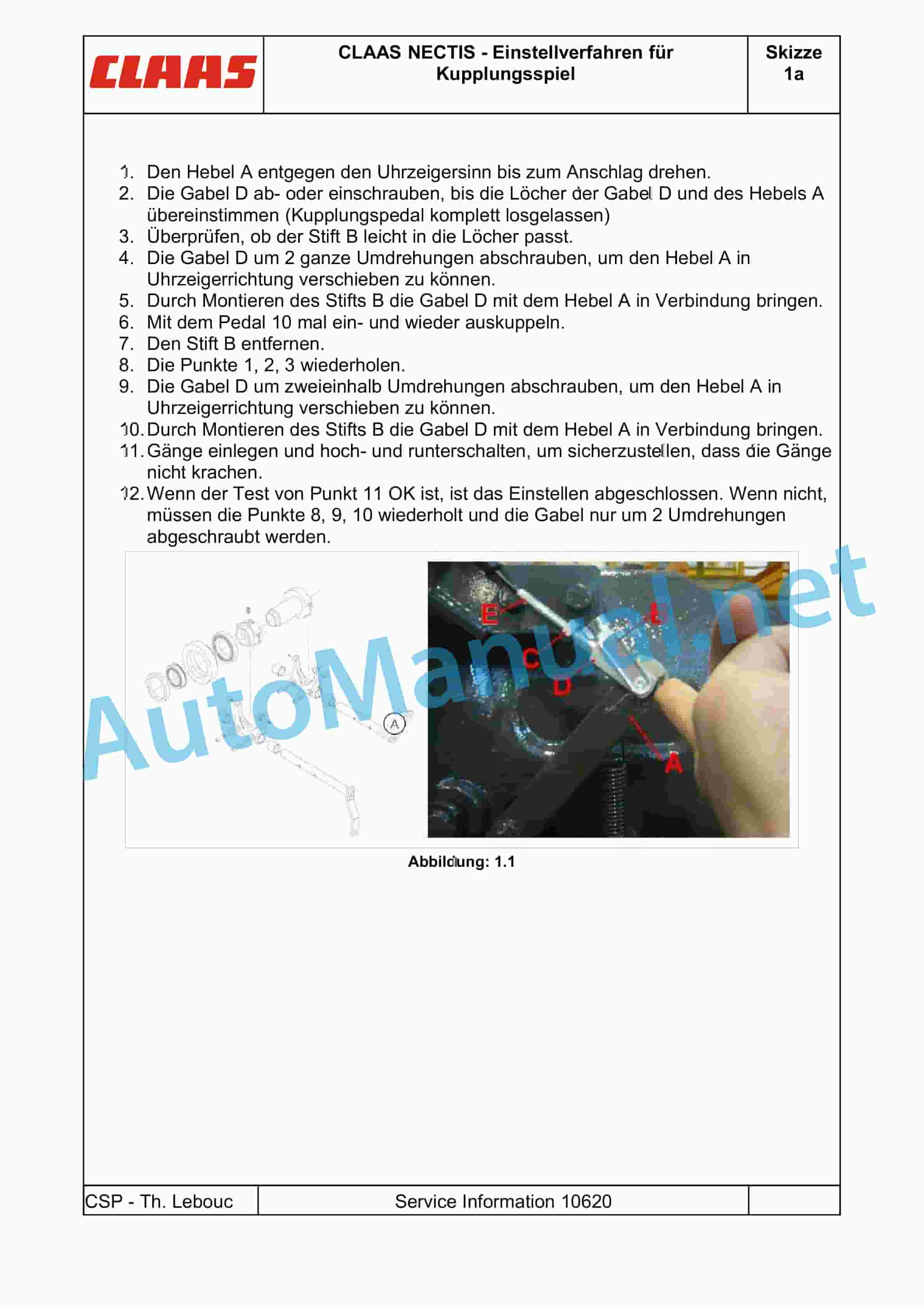
2 CLAAS NECTIS – Adjustment procedure for clutch play
Size(0.6 MB) 6.27.2011.pdf
Table of Content:
1 08 PTO SHAFT
2.1 FRONT PTO – NEXOS
2.2 FRONT PTO – ELIOS
Size(1 MB) 6.27.2011.pdf
Table of Content:
1 09 HYDRAULIC SYSTEM
1.1 CONTENT
1.2 Hydraulic circuit
Size(11.3 MB) 10.5.2010.pdf
Table of Content:
1 01 ENGINE – F5C
1.1 Introduction
1.2 General
1.3 Fuel supply
1.4 Motor peripherals
1.5 General overhaul of the engine
Size(2 MB) 6.27.2011.pdf
Table of Content:
1.1 TOOLS ACCORDING TO CHAPTER
1.2 TOOLS BY PART NUMBERS
Size ENGINE CABLE SET
1.7 W03 TRANSMISSION CABLE SET
1.8 W04 BLOWER AND AIR CONDITIONER HARNESS
1.9 W05 LIGHTING CABLE SET
1.10 W06 AIR BRAKE CABLE HARNESS
1.11 W08 AIR CONDITIONER COMPRESSOR CABLE HARNESS
1.12 W09 HITCH LATERAL SHIFT MAIN CABLE KIT
1.13 W09_2 SECOND CABLE SET OF HITCH LATERAL SHIFT
1.14 W11 2.4 GENERAL TECHNICAL DATA
2.5 Removal and installation
3 03_001-088_Chassis_4RM_Nexos-VL_DE.pdf
3.1 03 CHASSIS – Nexos VL ALL-WHEEL DRIVE
3.2 GENERAL INFORMATION
3.3 SAFETY INSTRUCTIONS
3.4 GENERAL TECHNICAL DATA
3.5 REMOVAL AND INSTALLATION
4 03_001-090_Chassis_4RM_Nexos-VE_DE.pdf
4.1 03 CHASSIS – Nexos VE ALL-WHEEL DRIVE
4.2 SAFETY INSTRUCTIONS
4.3 GENERAL INFORMATION
4.4 GENERAL TECHNICAL DATA
4.5 Removal and installation
Size(4.1 MB) 6.27.2011.pdf
Table of Content:
1 06 POWER LIFT
1.1 CONTENT
1.2 FRONT HITCH – NEXOS
1.3 FRONT LIFT – ELIOS
1.4 REAR LIFT
1.5 SAFETY INSTRUCTIONS
1.6 GENERAL INFORMATION
1.7 GENERAL TECHNICAL DATA
1.8 HYDRAULIC SYSTEM
1.9 MECHANICAL SYSTEMS
Size(50.5 MB) 9.6.2022.pdf
Table of Content:
1 Repair manual
2 Table of Contents
3 CCN (CLAAS COMPONENT NUMBER)
4 Intro Technical data
5 01 Motor
5.1 0102 Complete component
5.2 0125 Injection/fuel system
5.3 0135 cooling system
5.4 0145 air intake
5.5 0150 engine attachments
6 01 Motor
6.1 0102 Complete component
6.2 0110 Motor housing
6.3 0115 Motor Engine
6.4 0120 cylinder head / valves / distributor wheel
6.5 0125 Injection / Fuel System
6.6 0130 lubricating oil system
6.7 0135 cooling system
6.8 0140 exhaust system
6.9 0145 air intake
6.10 0150 engine attachments
6.11 0155 Motor control
7 01 Motor
7.1 0102 Complete component
7.2 0110 Motor housing
7.3 0115 Motor Engine
7.4 0120 cylinder head / valves / distributor wheel
7.5 0125 Injection / Fuel System
7.6 0130 lubricating oil system
7.7 0135 cooling system
7.8 0140 exhaust system
7.9 0145 air intake
7.10 0150 engine attachments
7.11 0155 Motor control
8 02 Gearbox / clutch / cardan shaft
8.1 0202 Complete component
8.2 0215 Mechanical clutch
8.3 0218 Control / actuation clutch
8.4 0220 Mechanical reversing
8.5 0222 Hydraulic reversing
8.6 0230 Mechanical gears
8.7 0234 powershift transmission
8.8 0238 Control / actuation gearbox
8.9 0240 rear axle housing
8.10 0242 Differential
8.11 0248 Control / actuation rear axle
8.12 0250 Mechanical front axle drive
8.13 0252 Electro-hydraulic front axle drive
8.14 0255 Gearbox cooling system
8.15 0260 PTO shaft
9 03 Chassis
9.1 0310 Axis
9.2 0320 Steering axle
9.3 0325 Front steering drive axle
9.4 0340 front wheels
10 04 Brake
10.1 0405 Service brake
10.2 0415 parking brake
11 06 Lifting device
11.1 0605 rear power lift
11.2 0610 Front power lift
11.3 0615 Front loader
12 08 Drives
12.1 0802 Rear PTO
12.2 0804 Front PTO
13 09 Hydraulics
13.1 0910 Pumps
13.2 0920 Valves
14 12 Cab / Driver’s cab
14.1 1210 Cabin
14.2 1215 Driver’s cab
14.3 1240 Air conditioning
15 80 attachments, machine housing
15.1 8025 fairings / hoods
15.2 8035 Ballast / additional weight
Size(70.3 MB) 6.27.2011.pdf
Table of Content:
1 02 TRANSMISSION AND GEARS
2 SAFETY INSTRUCTIONS
2.1 General security recommendations
2.2 Safety symbols
2.3 General precautions
3 GENERAL INFORMATION
3.1 Using the manual
3.2 Agreements and definitions
3.3 General description
3.4 Special recommendations
4 GENERAL TECHNICAL DATA
4.1 Technical features
4.2 Tightening torques, sealants and grease
4.3 Module data
5 REMOVAL AND INSTALLATION
5.1 4WD transfer case
5.2 Axle drive
5.3 Replacing the Teflon seals (clutch shaft)
5.4 Top covers and swing shaft
5.5 External gear 5.8 Synchronized Doppler
5.9 PTO shaft
5.10 Slave cylinder
5.11 Parking brake
5.12 Housing sensors
5.13 Differential lock control
5.14 Internal gearshift
5.16 switching group (primary shaft)
5.17 Input shaft
5.18 Synchronous. Reversing circuit
5.19 gears (primary shaft)
5.20 Differential assembly
5.21 Pinion – groups (secondary shaft)
5.22 gears (secondary shaft)
Size(8.9 MB) 10.13.2010.pdf
Table of Content:
1 01 ENGINE – NEF
1.1 Introduction
1.2 General
1.3 Fuel supply
John Deere Repair Technical Manual PDF
John Deere Repair Technical Manual PDF
John Deere PowerTech M 10.5 L and 12.5 L Diesel Engines COMPONENT TECHNICAL MANUAL CTM100 10MAY11
John Deere Repair Technical Manual PDF
John Deere DF Series 150 and 250 Transmissions (ANALOG) Component Technical Manual CTM147 05JUN98
John Deere Repair Technical Manual PDF
John Deere POWERTECH E 4.5 and 6.8 L Diesel Engines TECHNICAL MANUAL 25JAN08
John Deere Parts Catalog PDF
John Deere Tractors 7500 Parts Catalog CPCQ26568 30 Jan 02 Portuguese
John Deere Repair Technical Manual PDF
John Deere Repair Technical Manual PDF
John Deere Application List Component Technical Manual CTM106819 24AUG20
John Deere Repair Technical Manual PDF
John Deere Parts Catalog PDF
John Deere Tractors 6300, 6500, and 6600 Parts Catalog CQ26564 (29SET05) Portuguese

