Claas Torion 639 (K66) Wheel Loaders Technical System EN
$300.00
- Model: Torion 639 (K66) Wheel Loaders
- Type Of Manual: Technical System
- Language: EN
- Format: PDF(s)
- Size: 30.4 MB
File List:
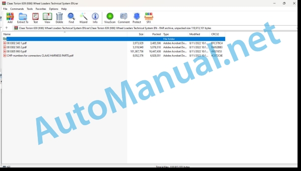
00 0302 343 1.pdf
00 0302 565 2.pdf
00 0305 993 0.pdf
CHP-numbers for connectors CLAAS HARNESS PARTS.pdf
00 0302 343 1.pdf:
PROFI CAM 3
Table of contents
General information
Marking of warnings and hazard prevention notes
First-aid measures
CCN explanation
CCN (CLAAS Component Number)
Electric system standard
Overview
Hydraulic system standard
Overview
CCN (CLAAS Component Number)
10 Electrical / Electronic equipment
1030 Board computer / Indicators
Camera system
Description of function
1097 Testing / Measuring / Adjusting
Testing / measuring / adjusting the PROFI CAM
Checking the fuse in the video channel select box (C102)
Testing the video camera connector (C055)
1098 Fault / remedy
Fault / remedy PROFI CAM
The video monitor (C101) shows no image or cannot be switched on (indicator light fails to light up)
Video monitor (C102) displays a blue image either permanently or temporarily
The video monitor image is blurred
Replacing the fuse in the video channel select box (C102)
Connection and connecting cable with video camera (C055)
00 0302 565 2.pdf:
Sensor system
Table of contents
CCN explanation
CCN (CLAAS Component Number)
Electric system standard
Overview
Hydraulic system standard
Overview
CCN (CLAAS Component Number)
Introduction
Safety rules
Safety and hazard information
10 Electrical / Electronic equipment
1097 Testing / Measuring / Adjusting
Test report of the angle sensor (0011780.x)
Application of test report
Required tools
Test report of the angle sensor (0011780.x)
Testing / Measuring / Adjusting of angle sensor (0011780.x)
1. Reason for test
2. Mechanical test of angle sensor
3. Electric test with CDS
4. Electric test with multimeter
5. Mechanical test of connecting cable
Completing the machine
Test report of position and speed sensors
Application of test report
Required tools
Sensor variants
Part numbers of speed sensors
Part number of position sensor
Test report of position and speed sensors
Testing / measuring / adjusting of position and speed sensors
1. Reason for test
2. Mechanical test
3. Electric test with CDS
4a. Installation dimensions
Check of installation dimension
Installation dimensions of gearbox speed sensor (0011 799.x) and cam speed sensor (0011 810.x)
Installation dimension of position sensor (0011 815.x)
4b. Installation position
Centring of sensor
Metal-free zone
5. Electric test with multimeter
Voltage measurement
Direction of rotation and speed sensor (0011 605.x)
Measured values table
6. Mechanical test of connecting cable
Completing the machine
Test report of the urea sensor (00 0773 207 x)
Application of test report
Required tools
Parts number of the urea sensor
Test report of the urea sensor
Testing / measuring / adjusting urea sensor
1. Reason for test
2. Mechanical test
3. Mechanical test of connecting cable
4. Electric test with multimeter
5. Component test with the CDS
00 0305 993 0.pdf:
Technical systems
Table of contents
Introduction
Notes on the manual
Validity of manual
Information about this Technical Systems Manual
Using the manual
Document structure based on subassemblies
Search and find
Directions
Identifying warnings
Hazard signs
Signal word
Safety rules
Safety signs and warnings
Requirement made on technical staff
Children in danger
Hazard areas of the machine
Instructors travelling along during fieldwork
Risk of injury from rotating shafts
Structural alterations of the machine
Optional equipment and spare parts
Control of running machine
Technical condition
Respecting technical limit values
Danger from machine parts that continue rotating
Keeping safety devices functional
Personal protective equipment
Wearing suitable clothing
Removing dirt and loose objects
Parking the machine safely
Unsuitable operating utilities
Safe handling of service fluids and auxiliary utilities
Environmental protection and disposal
Keeping the cab free of chemicals
Avoiding fires
Potentially fatal electric shock from overhead lines and lightning strike
Electric shock from electric system
Noise may damage your health
Pre-loaded machine parts
Liquids under pressure
Compressed air
Toxic exhaust gases
Hot surfaces
Safe access and leaving
Working only on the stopped machine
Hazards during repairs
Raised machine parts and loads
Danger from welding work
Checking and charging the battery
Preparations for cases of emergency
CCN explanation
CCN (CLAAS Component Number)
Electric systems standard
Overview
Hydraulic system standard
Overview
CCN (CLAAS Component Number)
01 Engine
0125 Injection / Fuel system
Fuel system
Measured values table
Description of function
0155 Engine control
Electronic engine control
Measured values table
Description of function
0165 Exhaust gas aftertreatment
Exhaust gas treatment
0197 Test/Measurement/Setting
Engine test report
Important notes and preparation
Test report type K64
Test report type K65, K66
Testing and adjusting the drive
Checking the diesel engine speeds
Diesel particulate filter service regeneration
03 Chassis
0335 Ground drive
Ground drive type K64
Measured values table
Description of function
Ground drive type K65, K66
Measured values table
Description of function
Ground drive pump type K64
Ground drive pump type K65, K66
Ground drive motor type K64
Ground drive motor type K65, K66
0397 Testing / measuring / adjusting
Ground drive test report
Important notes and preparation
Test report type K64
Test report type K65, K66
Testing and adjusting the ground drive type K64
Adjusting the pedals
Accelerator pedal
Inching pedal
Testing the deviation of the drive pump pressure sensor
Testing and adjusting the drive pump
Charge pressure limiting valve
Drive pump block curve adjustment
Adjustment of ground drive motor
Testing and adjusting the ground drive type K65, K66
Adjusting the pedals
Accelerator pedal
Inching pedal
Testing the deviation of the drive pump pressure sensor
Testing and adjusting the drive pump
Charge pressure limiting valve
Drive pump block curve adjustment
Adjustment of ground drive motor
04 Brake
0400 Brake
Brake type K64
Measured values table
Description of function
Brake type K65, K66
Measured values table
Description of function
0497 Testing / measuring / adjusting
Brake system test report
Important notes and preparation
Test report type K64
Test report type K65, K66
Testing and adjusting the brake system type K64
Testing and adjusting the brake system type K65, K66
05 Steering
0505 Steering
Steering type K64
Description of function
Steering type K65, K66
Description of function
06 Lift device
0630 Lift arms
Working attachment type K64
Description of function
Working attachment type K65, K66
Description of function
0697 Testing / measuring / adjusting
Working hydraulics test report
Important notes and preparation
Test report type K64
Test report type K65, K66
Testing and adjusting the working hydraulics type K64
Testing and adjusting the control block
Checking the control block for leaks
Stabilisation module
Testing the shut-off function
Testing the vibration damping hydraulic accumulator
Testing and adjusting the working hydraulics type K65, K66
Testing and adjusting the control block
Checking the control block for leaks
Stabilisation module
Testing the shut-off function
Testing the vibration damping hydraulic accumulator
09 Hydraulic system
0920 Valves
Working hydraulics control block
Stabilisation module
Description of function
0980 Hydraulic circuit diagram
Working hydraulics type K64 circuit diagram
Working hydraulics with electric 3rd and 4th function
Working hydraulics type K65, K66 circuit diagram
Working hydraulics with electric 3rd and 4th function
Ground drive hydraulics type K64 circuit diagram
Ground drive hydraulics type K65, K66 circuit diagram
Steering hydraulics type K64 circuit diagram
Steering hydraulics type K65, K66 circuit diagram
Braking hydraulics type K64 circuit diagram
Braking hydraulics type K65, K66 circuit diagram
0997 Testing / measuring / adjusting
Testing the hydraulic accumulator nitrogen filling
10 Electrical / Electronic equipment
1012 Modules / sensors
Module A10-LBH – Display
Key to diagram
Key to diagram
A200-LBH module – Central control unit
Key to diagram
Key to diagram
Module A201-LBH – central control unit
Key to diagram
Key to diagram
1080 Electrical circuit diagram
Electric circuit diagrams of machine (SCM)
SCM 12 – Power supply
Key to diagram
SCM 13 – Alternator charging light, buzzer
Key to diagram
SCM 14 – Reversing warning device
Key to diagram
SCM 15 – Control lever
Key to diagram
SCM 16 – Direction of travel
Key to diagram
SCM 17 – Accelerator pedal, inching function
Key diagram
SCM 18 – Drive ranges, drive speed sensor
Key to diagram
SCM 19 – Fuel level, 1st gear switch
Key to diagram
CM 20 – Turn signal indicator syste Key to diagram
SCM 21 – Front windscreen wiper, horn
Key to diagram
SCM 22 – Rear windscreen wiper
Key to diagram
SCM 23 – Rear work lights, interior lighting
Key to diagram
SCM 24 – Front work lights, lift arms additional light
Key to diagram
CM 25 – Drive lights
Key to diagram
SCM 26 – Air filter pollution, hydraulic oil temperature
Key to diagram
SCM 27 – CAN, diagnosis
Key to diagram
SCM 28 – Control lever power supply, working hydraulics lock, vibration damping
Key to diagram
SCM 29 – Broadcast radio, driver’s seat, 12 V socket
Key to diagram
SCM 30 – Rear-window heater, USB charge connection
Key to diagram
SCM 31 – Heater and air conditioner (machine side)
y to diagram
SCM 32 – Heater and air conditioner (system side)
CM 33 – Quick-hitch plate
Key to diagram
SCM 34 – Parking brake
Key to diagram
SCM 35 el particulate filter regeneration
Key to diagram
SCM 37 – Display lighting
Key to diagram
SCM 38 – Spare relay / fuses
Key to diagram
SCM 41 – Central control unit power supply
Key to diagram
SCM 42 – Central control unit 2 power supply
Key to diagram
SCM 45 – Electric starting motor, alternator, pre-heating system, exhaust gas recirculation
Key to diagram
SCM 46 – Diesel particulate filter monitoring
Key to diagram
SCM 47 – Engine oil pressure, fuel pump
Key to diagram
SCM 48 – Diesel engine transfer plug X36
Key to diagram
SCM 49 – Diesel engine transfer plug X37
Key to diagram
SCM 50 – Diesel engine transfer plug X38
Key to diagram
SCM 51 – Diesel engine tran plug X39
Key to diagram
CM 52 – Engine power supply/earth
Key to diagram
SCM 53 – Warning beacon option
Key to diagram
SCM 55 – Trailer hitch option, 12ocket option
Key to diagram
SCM 56 – Flashlight option
Key to diagram
SCM 57 – Contour lights option
Key to diagram
CM 58 – Central lubrication system, pipe break protection device
Key to diagram
SCM 59 – 3rd control circuit, control lever fixing
Key to diagram
SCM 60 – 3rd / 4th control circuit enable, working hydraulics pressure limitation
Key to diagram
SCM 61 – 3rd / 4th control circuit solenoid valves
Key to diagram
SCM 62 – Speed limitation option, rear additional function
Key to diagram
SCM 63 – 4th control circuit
Key to diagram
SCM 64 – Road sweeper option
Key to diagram
SCM 66 – OBD diagnostic plug and telemetry system
Key to diagram
SCM 68 – Fuel tearth
Key to diagram
SCM 72 – Pressureless return line option
Key to diagram
1085 Networks
Description of function
12 Cab / Operator’s platform
1240 Air coion
Heating, ventilation, air conditioning system
Description of function
92 Diagnosis
9210 Error codes machine
Fault codes
CHP-numbers for connectors CLAAS HARNESS PARTS.pdf:
CLAAS HARNESS PARTS
Table of contents
10 Electrical / Electronic equipment
1081 Overview of connectors
CLAAS HARNESS PARTS (CHP)
John Deere Repair Technical Manual PDF
John Deere 18-Speed PST Repair Manual Component Technical Manual CTM168 10DEC07
John Deere Repair Technical Manual PDF
John Deere Repair Technical Manual PDF
John Deere Transmission Control Unit Component Technical Manual CTM157 15JUL05
John Deere Parts Catalog PDF
John Deere Tractors 6300, 6500, and 6600 Parts Catalog CQ26564 (29SET05) Portuguese
John Deere Repair Technical Manual PDF
John Deere Application List Component Technical Manual CTM106819 24AUG20
John Deere Repair Technical Manual PDF
John Deere 16, 18, 20 and 24HP Onan Engines Component Technical Manual CTM2 (19APR90)
John Deere Repair Technical Manual PDF
John Deere Parts Catalog PDF
John Deere Tractors 7500 Parts Catalog CPCQ26568 30 Jan 02 Portuguese
John Deere Repair Technical Manual PDF
John Deere Diesel Engines PowerTech 4.5L and 6.8L – Motor Base Technical Manual 07MAY08 Portuguese

