Claas Tucano 560-550 (L36) Combines Repair Manual ES
$300.00
- Model: Tucano 560-550 (L36) Combines
- Type Of Manual: Repair Manual
- Language: ES
- Format: PDF(s)
- Size: 322 MB
File List:
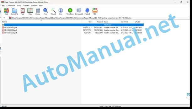
00 0301 541 1.pdf
00 0302 653 2.pdf
00 0303 732 0.pdf
00 0301 541 1.pdf:
Mercedes-Benz OM936LA(Level IV and V)
Introduction
General information
Manual validity
Using the manual
Texts and figures
Division with construction group structure
Search and find
Direction signs
Abbreviations
Technicalities
General repair instructions
Technical instructions
Indications for correct repair
Self-locking screws
Liquid screw insurance
Steel roller chains
connecting link
Type E connecting link with spring
Type G connecting link with wire
S type connecting link with pins
Tapered ring joints
Disassembly
Mounting
Head key joints
Disassembly
Mounting
Bearings with tension ring
Disassembly
Mounting
Bearing with tensioner sleeve
Disassembly
Mounting
Tension bushing
Disassemble
Disassembly version A
Disassembly version B
Tension bushing version A
Tension bushing version B
Safety rings
Screw connections with adjustment ring
Screw connections with non-sealed adjusting ring
Screw connections with sealing cone
Hydraulic hoses
Laying of hoses
Joint surface work
Replacement parts
Tightening torques
Tightening torques for ISO metric threads
Tightening torques for metric fine thread
Tightening torques for fittings with tapered seal connection and hydraulic connections with soft seal ring
Tightening torques for hydraulic bolted connections with cutting ring
Tightening torques for SDS form B and E hydraulic threaded fittings
Tightening torques for oscillating hydraulic threadings
Tightening torques for hollow screws (with copper gasket)
Tightening torques for SDE form H hydraulic threaded fittings, adjustable
Tightening torques for brake pipe threading
Tightening torques for helical thread clamps
Tightening torques for hose clamps with round bolt
CCN Explanation
CCN (CLAAS Component Number)
General indications
Electrical regulations
Hydraulic regulations
CCN (CLAAS Component Number)
Security
General information
Especially important
Danger symbols
Rules to avoid accidents with personal injury
General indications
Check, adjustment and repair work
Engine operation
Suspended loads
Work on pipes and hoses
Work on the Common Rail system
Electrical installation work
Work in the hydraulic installation
Electric welding
lacquer work
Work with urea solution
Tips on how to avoid damage and premature wear
General indications
Limitation of liability
General indications
Immobilization and storage
Prescriptions to avoid damage to health and the environment
Prevention measures to protect against health and environmental damage
Disposal of consumables and auxiliary consumables
Instructions for working on the diesel engine
Protection against accidents
Cleaning
Assembly instructions
Engine check
Commissioning after an engine overhaul
First aid measures
01 Engine
0102 Complete component
Engine characteristic data
OM 936 LA
Engine Description
engine components
engine components
Actuators
Power-on sequence
turn the engine
Special tool with motor mounted
Special tool with the engine removed
Special tool place the engine at the top dead center of the ignition
Turn the engine in assembled state
Turn the engine in disassembled state
Place the engine at the top dead center of the ignition
Place the engine at top dead center of the ignition: Disassemble
0105 Engine suspension
Hooking rings
Technical instructions
0110 Engine casing
Technical instructions
special tool
Disassemble
Front crankshaft gasket
Technical instructions
special tool
Disassemble
Rear crankshaft gasket
Technical instructions
special tool
Disassemble
Housing cover
Technical instructions
special tool
Disassemble
control box
Technical instructions
Preparation for work
Disassemble
flywheel housing
Technical instructions
special tool
Disassemble
0115 Engine propulsion
Technical instructions
special tool
Disassemble
Check test pressure
Connecting rod
Technical instructions
Disassemble
cylinder bore
Technical instructions
special tool
Crankshaft
Technical instructions
special tool
Disassemble the crankshaft
Check the crankshaft
Install the crankshaft
crankshaft main bearing
Technical instructions
special tool
Disassemble
Vibration damper
Technical instructions
special tool
Disassemble
flywheel
Technical instructions
special tool
Disassemble
0120 Cylinder head / valves / distributor wheel
cylinder head cover
Technical instructions
Disassemble
rocker frame
Technical instructions
Disassemble
Camshafts
Technical instructions
special tool
Disassemble
Technical instructions
special tool
Disassemble
rocker mechanism
Technical instructions
Disassemble
Technical instructions
special tool
Disassemble
Check the valves
Adjust valve clearance
Valve springs and valve stem seals
Technical instructions
special tool
Disassemble
toothed transmission
Technical instructions
Disassemble
Check and adjust the play of the toothed sides
0125 Fuel/injection system
High pressure pipes and rail
Technical instructions
special tool
Disassemble
Injectors
Technical instructions
Preparation for work
special tool
Disassemble
Protective cap
Technical instructions
special tool
Disassemble
Fuel pump (low pressure)
Technical instructions
Preparation for work
Disassemble
Fuel pump (high pressure)
Technical instructions
Preparation for work
special tool
Disassemble
Fuel pump drive sprocket (high pressure)
Technical instructions
Preparation for work
special tool
Disassemble
fuel filter module
Technical instructions
Preparation for work
Disassemble
Fuel preheating heating element
Technical instructions
Preparation for work
Disassemble
Quantity regulating valve (Y643-MB)
Technical instructions
Preparation for work
Disassemble
Testing device for measuring fuel pressure
Technical instructions
Preparation for work
special tool
0130 Lubricating oil system
Lubricating oil system
special tool
Oil injection nozzle
Technical instructions
Disassemble
Oil-coolant module
Technical instructions
Preparation for work
Remove the oil-coolant module
Install the oil-coolant module
Disassemble the heat exchanger
Assemble the heat exchanger
Oil pump
Technical instructions
Preparation for work
Disassemble
0135 Cooling system
Cooling agent
special tool
Fill out
Clean the coolant circuit
Coolant pump
Technical instructions
Preparation for work
Disassemble
Coolant thermostat
Technical instructions
Preparation for work
Disassemble
0140 Exhaust gas system
Exhaust gas return radiator
Technical instructions
Preparation for work
special tool
Remove the exhaust gas return pipe behind the exhaust gas return radiator
Install the exhaust gas return pipe behind the exhaust gas return radiator
Remove the exhaust gas return pipe in front of the exhaust gas return radiator
Install the exhaust gas return pipe in front of the exhaust gas return radiator
Remove the exhaust gas return radiator
Install the exhaust gas return radiator
Check the possible pressure loss in the exhaust gas return radiator
Exhaust gas return radiator support
Technical instructions
Preparation for work
Remove the exhaust gas return radiator support
Install the exhaust gas return radiator support
Exhaust gas return radiator support
Technical instructions
Preparation for work
Remove the exhaust gas return radiator support
Install the exhaust gas return radiator support
exhaust gas elbow
Technical instructions
Preparation for work
Disassemble
exhaust gas elbow
Technical instructions
Preparation for work
Disassemble
Exhaust gas turbocharger
Technical instructions
Preparation for work
Disassemble
Exhaust gas turbocharger
Technical instructions
Preparation for work
Disassemble
Intake pressure regulator
Technical instructions
Preparation for work
Disassemble
Exhaust Gas Return Actuator (Y621-MB)
Technical instructions
Preparation for work
Disassemble
Exhaust gas turbocharger oil lines
Technical instructions
Preparation for work
Disassemble
Exhaust gas turbocharger oil lines
Technical instructions
Preparation for work
Disassemble
0145 Air suction
Air intake housing
Technical instructions
Preparation for work
Remove the intake air pipe on the left
Install the intake air pipe on the left
Remove the intake air pipe on the right
Install the intake air pipe on the right
Remove the intake air distributor
Install the intake air distributor
0150 Engine coupled parts
Starting motor
Technical instructions
Disassemble
Generator (G002, G003/G2-MB)
Technical instructions
special tool
Disassemble the generator
Assemble the generator
Belt tensioner for generator drive belt
Technical instructions
Assembly instructions
Resonance vessel
Technical instructions
Assembly instructions
Air compressor
Technical instructions
Preparation for work
special tool
Disassemble the air compressor
Assemble the air compressor
Remove the drive pinion
Install the drive sprocket
0155 Engine adjustment
Control command
Technical instructions
Assembly instructions
0165 Exhaust gas aftertreatment
Urea pump (M047/M25-MB)
Technical instructions
Preparation for work
special tool
Disassemble the urea pump
Assemble the urea pump
Remove the pressure limiting valve
Install the pressure relief valve
Remove the filter from the inlet fitting
Install the inlet fitting filter
Remove the antifreeze element
Install the antifreeze element
Urea Dosing Unit (A089/A67-MB)
Technical instructions
Preparation for work
special tool
Disassemble the dosing unit
Assemble the dosing unit
Disassemble the filter
Install the filter
00 0303 732 0.pdf:
TUCANO 580 / 570 / 560TUCANO 450 / 430MONTANA
Introduction
General information
Manual validity
Using the manual
Texts and figures
Division with construction group structure
Search and find
Direction signs
Abbreviations
Technicalities
General repair instructions
Technical instructions
Indications for correct repair
Self-locking screws
Liquid screw insurance
Steel roller chains
connecting link
Type E connecting link with spring
Type G connecting link with wire
S type connecting link with pins
Tapered ring joints
Disassembly
Mounting
Head key joints
Disassembly
Mounting
Bearings with tension ring
Disassembly
Mounting
Bearing with tensioner sleeve
Disassembly
Mounting
Tension bushing
Disassemble
Disassembly version A
Disassembly version B
Tension bushing version A
Tension bushing version B
Safety rings
Screw connections with adjustment ring
Screw connections with non-sealed adjusting ring
Screw connections with sealing cone
Hydraulic hoses
Laying of hoses
Radial shaft seal rings
Joint surface work
Drive belts / drive chains
Diesel engine
Generator
Replacement parts
Cause of the fault
Tightening torques
Tightening torques for ISO metric threads
Tightening torques for metric fine thread
Tightening torques for hydraulic bolted connections with cutting ring
Tightening torques for fittings with tapered seal connection and hydraulic connections with soft seal ring
Tightening torques for hydraulic screw connections with hoses and pipes with soft sealing ring
Hydraulic bolt nut tightening torques for bulkhead fittings, straight and angled
Tightening torques for SDS form B and E hydraulic threaded fittings
Tightening torques for SDS form F hydraulic threaded fittings
Tightening torques for SDS form H hydraulic threaded fittings
Tightening torques for SDE form F hydraulic threaded fittings, with adjustable direction
Tightening torques for SDE form H hydraulic threaded fittings, adjustable
Tightening torques for oscillating hydraulic threadings
Tightening torques for hollow screws (with copper gasket)
Tightening torques for brake pipe threading
Tightening torques for pipe supports with O-ring and union nuts
Tightening torques for helical thread clamps
Tightening torques for hose clamps with round bolt
Tightening torques for wheels
Technical data
Consumables
CCN Explanation
CCN (CLAAS Component Number)
General indications
Electrical regulations
Hydraulic regulations
CCN (CLAAS Component Number)
Security
General information
Especially important
Signage of warning and danger indications
General safety measures and accident prevention rules
Safety measures and accident prevention in combine harvesters
First aid measures
Unloading of the harvest / unloading of the chaff
Leave the machine
grain warehouse
Combine chopper device
Adjustment and maintenance work
Risk of injury from hydraulic fluid
Air conditioning equipment
pressure accumulator
Battery separator switch
Install the safety support of the feeding channel
Raise the machine on supports
Put the machine out of service
Welding work
03 Chassis
0315 Drive axle
Identify the drive axle
Technical instructions
Differential
Technical instructions
Preparation for work
special tool
Disassemble
Differential concave
Technical instructions
Disassemble
Differential lock
Technical instructions
Preparation for work
special tool
shift cylinder
Technical instructions
Preparation for work
axle carrier
Technical instructions
Preparation for work
Disassemble
Axle connecting rod outer part
Technical instructions
Preparation for work
special tool
Disassemble
BB planetary drive
Technical instructions
Preparation for work
Disassemble
04 Brake
0405 Service brake
Brake cylinder
Technical instructions
Preparation for work
Disassemble
Check the wear of the brake discs
Bleed the brake cylinder
Drain leaking oil
John Deere Repair Technical Manual PDF
John Deere Application List Component Technical Manual CTM106819 24AUG20
John Deere Repair Technical Manual PDF
John Deere Diesel Engines PowerTech 4.5L and 6.8L – Motor Base Technical Manual 07MAY08 Portuguese
John Deere Repair Technical Manual PDF
John Deere 18-Speed PST Repair Manual Component Technical Manual CTM168 10DEC07
John Deere Parts Catalog PDF
John Deere Tractors 6300, 6500, and 6600 Parts Catalog CQ26564 (29SET05) Portuguese
John Deere Parts Catalog PDF
John Deere Tractors 7500 Parts Catalog CPCQ26568 30 Jan 02 Portuguese
John Deere Repair Technical Manual PDF
John Deere Parts Catalog PDF
John Deere Harvesters 8500 and 8700 Parts Catalog CPCQ24910 Spanish
John Deere Repair Technical Manual PDF
John Deere Repair Technical Manual PDF
John Deere Repair Technical Manual PDF
John Deere Transmission Control Unit Component Technical Manual CTM157 15JUL05


