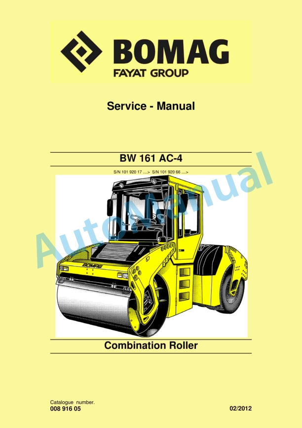
Bomag BW 161 AC-4 Combination Roller Service Manual 00891605
$30.00
- Type Of Manual: Service Manual
- Manual ID: 00891605
- Format: PDF
- Size: 43.8MB
- Number of Pages: 864
- Serial Number:
10192017 and up
10192066 and up
Category: Bomag Service Manual PDF
-
Model List:
- BW 161 AC-4 Combination Roller
- 1. BW 161 AC4
- 1.1. BW 161 AC4
- 2. General
- 2.1. General
- 2.2. Introduction
- 2.3. General
- 2.4. General
- 2.5. Transport work with cranes and lifting tackle
- 2.6. Precautions and codes of conduct for welding work
- 2.7. Operation of highvoltage systems
- 2.8. Old oils
- 2.9. Hydraulics
- 2.10. Hot fuels
- 2.11. Synthetic rubber
- 2.12. Poisonous substances
- 2.13. Air conditioning system
- 2.14. Battery
- 2.15. Special safety regulations
- 2.16. The values specified in the table apply for screws
- 2.17. The values specified in the table apply for screws
- 2.18. The values specified in the table apply for screws
- 2.19. The values specified in the table apply for screws
- 2.20. The values specified in the table apply for screws
- 2.21. The values specified in the table apply for screws
- 2.22. The values specified in the table apply for screws
- 2.23. The values specified in the table apply for screws
- 2.24. The values specified in the table apply for screws
- 2.25. The values specified in the table apply for screws
- 2.26. The values specified in the table apply for screws
- 2.27. The values specified in the table apply for screws
- 2.28. The values specified in the table apply for screws
- 2.29. The values specified in the table apply for screws
- 3. Pivot steered tandem rollers
- 3.1. Pivot steered tandem rollers
- 4. Technical data
- 4.1. Technical data
- 4.2.
- 4.3.
- 5. Maintenance
- 5.1. Maintenance
- 5.2. General notes on maintenance
- 5.3. Fuels and lubricants
- 5.4. Coolant
- 5.5. Mineral oil based hydraulic oil
- 5.6. Biodegradable hydraulic oil
- 5.7. Gear oil
- 5.8. Lubrication grease
- 6. Caddy wiring diagrams
- 6.1. Caddy wiring diagrams
- 7. Electrics
- 7.1. Electrics
- 7.2. DTM Series
- 7.3. DTM Series
- 7.4. DTM Series
- 7.5. DTM Series
- 7.6. DTM Series
- 7.7. DTM Series
- 7.8. DTM Series
- 7.9. DTM Series
- 7.10. DTM Series
- 7.11. DTM Series
- 7.12. DTM Series
- 7.13. DTM Series
- 7.14. DTM Series
- 7.15. DTM Series
- 7.16. DTM Series
- 7.17. DTM Series
- 7.18. DTM Series
- 7.19. Battery service, check the main battery switch
- 7.20. Battery service, check the main battery switch
- 7.21. Battery service, check the main battery switch
- 7.22. Battery service, check the main battery switch
- 7.23. Battery service, check the main battery switch
- 7.24. Battery service, check the main battery switch
- 7.25. Battery service, check the main battery switch
- 7.26.
- 7.27.
- 7.28. Starting with jump wires
- 7.29.
- 7.30.
- 7.31.
- 7.32.
- 7.33.
- 7.34.
- 7.35.
- 7.36.
- 7.37.
- 7.38.
- 7.39.
- 7.40. S01, Emergency stop switch
- 7.41.
- 7.42.
- 7.43.
- 7.44.
- 7.45.
- 7.46.
- 8. Electronic modules
- 8.1. Electronic modules
- 8.2.
- 8.3.
- 8.4.
- 8.5.
- 8.6.
- 8.7.
- 8.8.
- 8.9.
- 8.10.
- 8.11.
- 8.12.
- 8.13.
- 8.14.
- 8.15.
- 8.16.
- 8.17.
- 8.18.
- 8.19.
- 8.20.
- 8.21.
- 8.22.
- 8.23.
- 9. Speedometer Module
- 9.1. Speedometer Module
- 10. Hydraulics
- 10.1. Hydraulics
- 10.2. Variable displacement pump, A4VG56HW / A4VG28HW
- 10.3. Variable displacement pump, A4VG56HW / A4VG28HW
- 10.4. Variable displacement pump, A4VG56HW / A4VG28HW
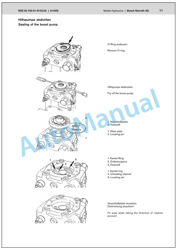
- 10.5. Variable displacement pumps, A10VG28/45/56 EZ
- 10.6. Variable displacement pumps, A10VG28/45/56 EZ
- 10.7. Swash plate principle
- 10.8. Swash plate principle
- 10.9. Functional principle radial piston motors, MS/MSE
- 10.10. Functional principle radial piston motors, MS/MSE
- 10.11. Vibration motor, MMF 025
- 10.12. Vibration motor, MMF 025
- 10.13. Vibration control valve
- 10.14. Vibration control valve
- 10.15. OSP steering valve
- 10.16. OSP steering valve
- 10.17. External gear pumps
- 10.18. External gear pumps
- 10.19. Multiple gear pumps
- 10.20. Towing
- 10.21. Outer gear motors nonreversible
- 10.22. Check the hydraulic oil level
- 10.23. Changing the hydraulic oil filter
- 10.24. Changing hydraulic oil and breather filter
- 11. Tests and adjustments
- 11.1. Tests and adjustments
- 12. Trouble shooting
- 12.1. Trouble shooting
- 13. Flushing and bleeding
- 13.1. Flushing and bleeding
- 13.2. Special tools for flushing
- 13.3. Bleeding the vibration circuit
- 13.4. Bleeding the vibration circuit
- 13.5. Bleeding the vibration circuit
- 14. Engine
- 14.1. Engine
- 14.2. Check, adjust the valve clearance
- 14.3. Check, adjust the valve clearance
- 14.4. Check, adjust the valve clearance
- 14.5. Check, adjust the valve clearance
- 14.6. Check, adjust the valve clearance
- 14.7. Check, adjust the valve clearance
- 14.8. Check, adjust the valve clearance
- 14.9. Check the engine oil level
- 14.10. Changing engine oil and oil filter
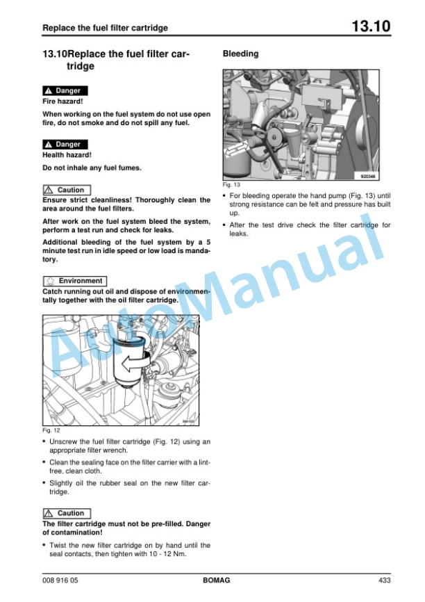
- 14.11. Replace the fuel filter cartridge
- 14.12. Change the fuel prefilter cartridge
- 14.13. Check the coolant level
- 14.14. Check the antifreeze concentration and the condition of the coolant
- 14.15. Change the coolant
- 14.16. Checking, cleaning radiator, fuel cooler and hydraulic oil cooler
- 14.17. Check the engine mounts
- 14.18. Servicing the Vbelt
- 14.19. Servicing the Vbelt for the refrigerant compressor
- 14.20. Check, clean, change the combustion air filter
- 14.21. Engine conservation
- 15. Air conditioning system
- 15.1. Air conditioning system
- 15.2. Checking, tensioning, replacing the refrigerant compressor Vbelt
- 15.3. Checking, tensioning, replacing the refrigerant compressor Vbelt
- 15.4. Checking, tensioning, replacing the refrigerant compressor Vbelt
- 15.5. Checking, tensioning, replacing the refrigerant compressor Vbelt
- 15.6. Service the air conditioning
- 16. Replacing the cab window panes
- 16.1. Replacing the cab window panes
- 17. Replacing the travel control cable
- 17.1. Replacing the travel control cable
- 18. Drum
- 18.1. Drum
- 18.2. Special tools, drum (BW161AD4 to BW203AD4)
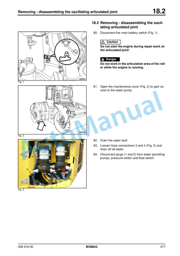
- 19. Oscillating articulated joint
- 19.1. Oscillating articulated joint
- 19.2. Repair overview oscillating articulated joint
- 19.3. Assembling the oscillating articulated joint
- 19.4. Assembling the oscillating articulated joint
- 20. Suppliers documentation
- 20.1. Suppliers documentation
- 21. Circuit diagrams
- 21.1. Circuit diagrams
- 21.2. S/N Hydraulic diagram 920 100 65
- 21.3. S/N Hydraulic diagram 920 100 65
- 21.4. S/N Hydraulic diagram 920 100 65
- 21.5. S/N Hydraulic diagram 920 100 65
- 21.6. S/N Wiring diagram 920 100 09
- 21.7. S/N Wiring diagram 920 100 09
- 21.8. S/N Wiring diagram 920 100 09
- 21.9. S/N Wiring diagram 920 100 09
- 21.10. S/N Wiring diagram 920 100 09
- 22.
- 22.1.
Rate this product
You may also like
Bomag Service Manual PDF
Bomag BC 473 RB-3 Refuse Compactor Electric Schematics Diagram 101930131001 – 101930139999
$30.00
Bomag Service Manual PDF
Bomag BC 473 EB-3 Refuse Compactor Electric Schematics Diagram 101930151001 – 101930159999
$30.00
Bomag Service Manual PDF
$30.00
Bomag Service Manual PDF
$30.00
Bomag Service Manual PDF
$30.00
Bomag Service Manual PDF
Bomag BC 472 RS Refuse Compactor Electric, Hydraulic Schematics Diagram 101930011002 – 101930011011
$30.00
Bomag Service Manual PDF
$30.00
Bomag Service Manual PDF
$30.00
Bomag Service Manual PDF
Bomag BC 572 RB Refuse Compactor Electric, Hydraulic Schematics Diagram 101570631001 – 101570631163
$30.00
Bomag Service Manual PDF
$30.00

