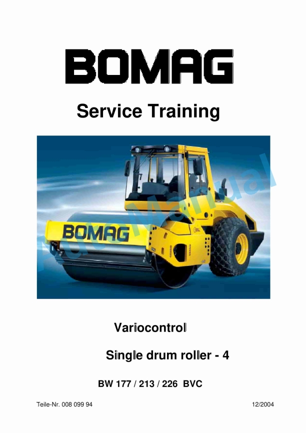
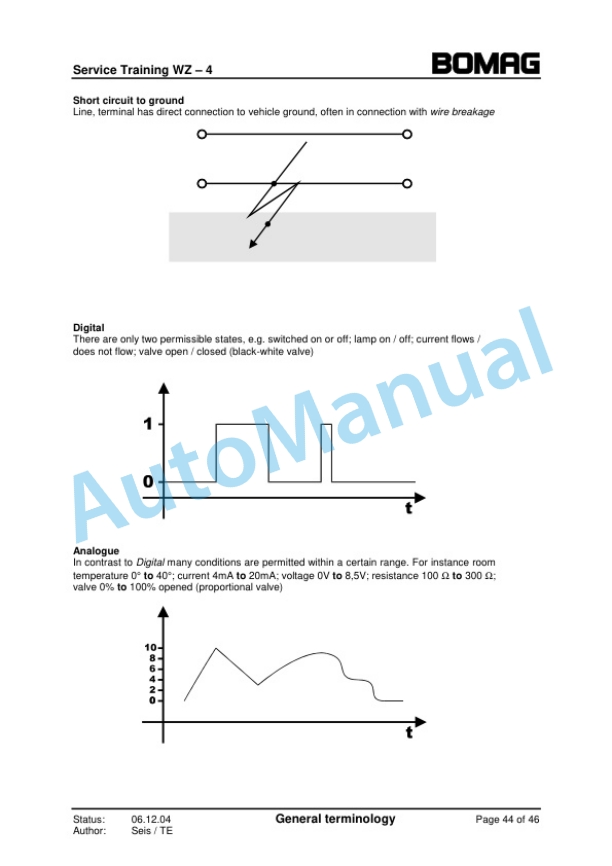
Bomag BW 177 BVC, BW 213 BVC, BW 226 BVC Single Drum Roller – 4 Variocontrol Service Training 00809994
$30.00
- Type Of Manual: Service Training
- Manual ID: 00809994
- Format: PDF
- Size: 6.1MB
- Number of Pages: 182
-
Model List:
- BW 177 BVC Single Drum Roller
- BW 213 BVC Single Drum Roller
- BW 226 BVC Single Drum Roller – 4 Variocontrol
- 0.1. Table of contents
- 1. Foreword
- 1.1. Foreword
- 1.2. Documentation
- 2. General
- 2.1. General
- 2.2. Specialities
- 3. Electric
- 3.1. Electric steering
- 3.2. Hydraulic steering circuit
- 3.3. Steering pump with filter
- 3.4. Steering wheel
- 3.5. Steering valve, electrically proportional
- 3.6. Steering angle sensor
- 4. Compaction
- 4.1. Compaction measuring system for single drum rollers
- 4.2. BTM plus
- 4.3. BTM prof
- 5. BVC_Sys.pdf
- 5.1. BVC System
- 5.2. Exciter unit
- 5.3. Swashing motor
- 5.4. with integrated potentiometer based distance measuring system
- 5.5. Acceleration transducer
- 5.6. BVC Circuit diagram for BW 177 DH4
- 5.7. BVC Circuit diagram for BW 213 / 226 DH4
- 5.8. Gear pump with high pressure filter
- 5.9. Valve block
- 5.10. MESXcontrol
- 5.11. BOP Bomag Operation Panel
- 6. Principle
- 6.1. Working principle of system
- 6.2. Repair and adjustments
- 7. Trouble_MESX.pdf
- 7.1. Trouble shooting
- 8. MESX_Schulung_V3.0
- 8.1. Document updating record
- 8.2. Software updating record
- 8.3. Known faults
- 8.4. How to proceed when replacing components
- 8.4.1. How to proceed when replacing an ESX control
- 8.4.2. How to proceed when replacing a rear axle sensor
- 8.4.3. Which components can be replaced without a subsequent adjustment procedure
- 8.4.4. List of machine types
- 8.5. Adjustment possibilities on machines without BOP
- 8.5.1. Description of the display module
- 8.5.2. Input of code numbers
- 8.5.3. Changing the machine type (only via display module)
- 8.5.4. Inverting the direction signal (only via display module)
- 8.5.5. Changing the bit rate (only with display module)
- 8.6. Adjustment/display possibilities on machines with BOP
- 8.6.1. Setting the machine type (BOP)
- 8.6.2. Inverting the direction signal via the BOP control terminal
- 8.6.3. Calling up the diagnostics menu
- 8.6.3.1. Extended diagnose for machines with circular exciter (BTMplus, BTMprof)
- 8.6.3.2. Extended diagnostics for BVC machines
- 8.6.4. Changing the printer language
- 8.6.5. Setting the machine serial number
- 8.6.6. Teaching distance impulses
- 8.7. Block diagram BEM
- 8.8. Block diagram BTMplus / VARIOCONTROL
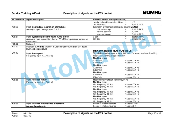
- 8.9. Description of the signals on the ESXcontrol
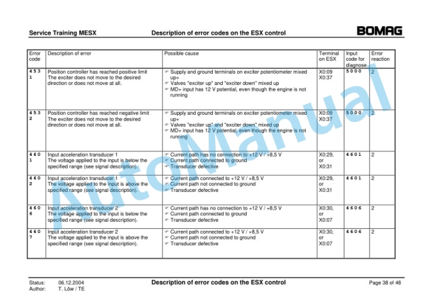
- 8.10. Error codes of the ESX control
- 8.10.1. Overview
- 8.10.2. Description of error reactions
- 8.10.3. Detailed description of fault codes and their possible causes
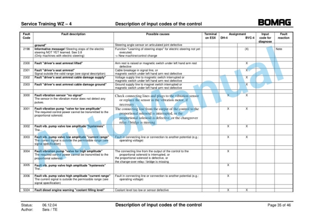
- 8.11. Input codes for ESX control (only via BEM display module)
- 8.11.1. Travel system
- 8.11.2. Vibration
- 8.11.3. Acceleration transducer
- 8.11.4. Diesel engine
- 8.11.5. Setting the machine type
- 8.11.6. Parameter change
- 8.12. Terminology in connection with ESX
- 9. ESX_Schulung_WZ4 V1.03
- 9.1. List of changes
- 9.2. Selected fault reactions of the ESX control
- 9.2.1. Calling up service mode
- 9.2.2. Entering input codes
- 9.2.3. Adjusting the machine type
- 9.2.4. Changing the steering unit on BVC4 machines (from version 1.09)
- 9.2.5. Teaching the travel direction sensor
- 9.2.6. Automatic detection of surge currents in the travel system
- 9.2.7. Automatic detection of surge currents on steering valves (BVC)
- 9.2.8. Teaching the electronic end stops of the steering angle sensor (BVC)
- 9.2.9. Driving against the closed brake
- 9.2.10. Showing stored faults
- 9.2.11. Deleting all stored faults
- 9.2.12. How to proceed when replacing an ESX control
- 9.2.13. How to proceed when replacing a travel pump / axle drive motor / drum drive motor
- 9.2.14. How to proceed when replacing a steering valve (BVC)
- 9.2.15. How to proceed when replacing a steering angle transducer
- 9.2.16. How to proceed when replacing an front / rear axle sensor
- 9.2.17. Which components can be replaced without a subsequent adjustment procedure
- 9.3. Description of the signals on the ESXcontrol
- 9.4. Description of signals on the data collector
- 9.5. Description of signals on the travel lever
- 9.6. Description of signals on the LC Display
- 9.7. Description of signals on the DIOS module (only with optional extension plates)
- 9.8. Fault codes of the ESX control
- 9.8.1. Overview
- 9.8.2. Description of fault reactions
- 9.8.3. Detailed description of fault codes and their possible causes
- 9.9. Input codes for ESX control
- 9.9.1. General
- 9.9.2. Travel lever / driving
- 9.9.3. Steering
- 9.9.4. Vibration
- 9.9.5. Hydraulics
- 9.9.6. Changing the machine code
- 9.10. Terminology in connection with ESX
- 10. Circuit diagram
- 11. Hydraulic diagram
Bomag Service Manual PDF
Bomag Service Manual PDF
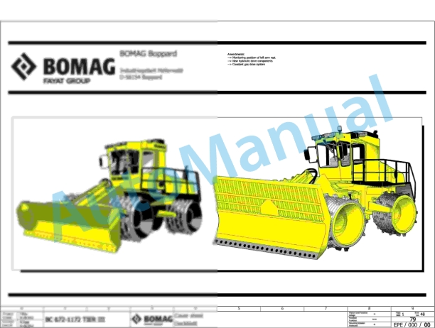
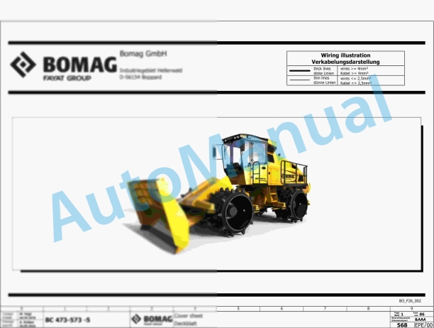
Bomag BC 473 EB-3 Refuse Compactor Electric Schematics Diagram 101930151001 – 101930159999
Bomag Service Manual PDF
Bomag BC 473 RB-3 Refuse Compactor Electric Schematics Diagram 101930131001 – 101930139999
Bomag Service Manual PDF
Bomag Service Manual PDF
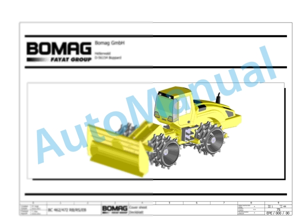
Bomag BC 462 EB Refuse Compactor Electric, Hydraulic Schematics Diagram 101930021001 – 101930021018
Bomag Service Manual PDF
Bomag Service Manual PDF
Bomag BC 463 RB-3 Refuse Compactor Electric Schematics Diagram 101930121001 – 101930129999
Bomag Service Manual PDF
Bomag Service Manual PDF
Bomag Service Manual PDF
Bomag BC 472 RS Refuse Compactor Electric, Hydraulic Schematics Diagram 101930051001 – 101930051010

