


Bomag BW 190 AD-4, BW 202 AD-4, BW 203 AD-4 Tandem Vibratory Roller Service Manual 00891468
$30.00
- Type Of Manual: Service Manual
- Manual ID: 00891468
- Format: PDF
- Size: 78.0MB
- Number of Pages: 1036
- Serial Number:
10192015 and up
10192065 and up
10192012 and up
10192063 and up
10192014 and up
10192064 and up
Bomag Service Manual PDF

Bomag Service Manual PDF
Bomag BC 462 EB Refuse Compactor Electric, Hydraulic Schematics Diagram 101930021001 – 101930021018
Bomag Service Manual PDF
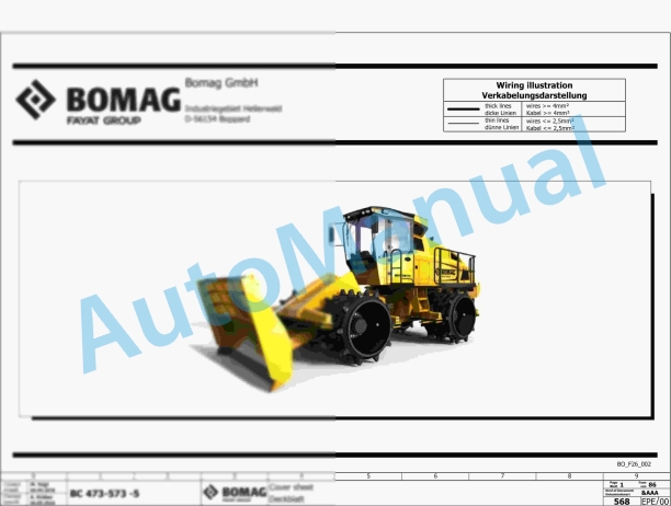
Bomag BC 473 EB-4 Refuse Compactor Electric Schematics Diagram 101930111001 – 101930119999
Bomag Service Manual PDF

Bomag Service Manual PDF
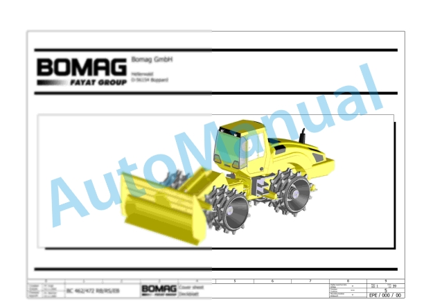
Bomag BC 462 RB Refuse Compactor Electric, Hydraulic Schematics Diagram 101930031001 – 101930031042

Bomag Service Manual PDF
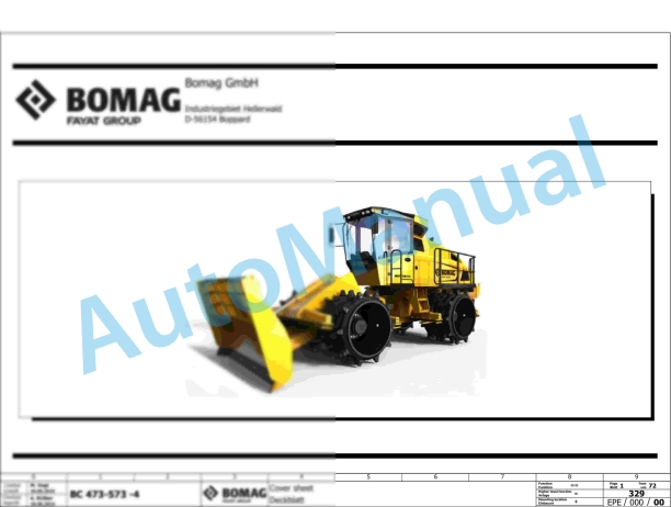
Bomag BC 473 EB-3 Refuse Compactor Electric Schematics Diagram 101930151001 – 101930159999
Bomag Service Manual PDF

Bomag Service Manual PDF
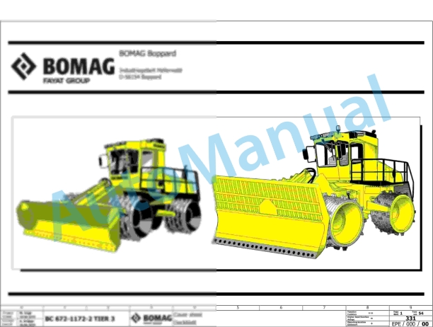
Bomag BC 472 RS Refuse Compactor Electric, Hydraulic Schematics Diagram 101930051001 – 101930051010
Bomag Service Manual PDF
Bomag Service Manual PDF
Bomag BC 472 RB Refuse Compactor Electric, Hydraulic Schematics Diagram 101930001002 – 101930001058