


Bomag BW 211 D-4, BW 211 PD-4, BW 213 D-4, BW 213 PD-4, BW 214 D-4 Single Drum Roller Service Training 00891882
$30.00
- Type Of Manual: Service Training
- Manual ID: 00891882
- Format: PDF
- Size: 26.5MB
- Number of Pages: 512
- Serial Number:
10158309 and up
10158310 and up
10158308 and up
10158313 and up
10158342 and up
10158415 and up
Bomag Service Manual PDF
Bomag Service Manual PDF
Bomag Service Manual PDF
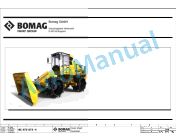
Bomag BC 473 RB-3 Refuse Compactor Electric Schematics Diagram 101930131001 – 101930139999
Bomag Service Manual PDF
Bomag Service Manual PDF
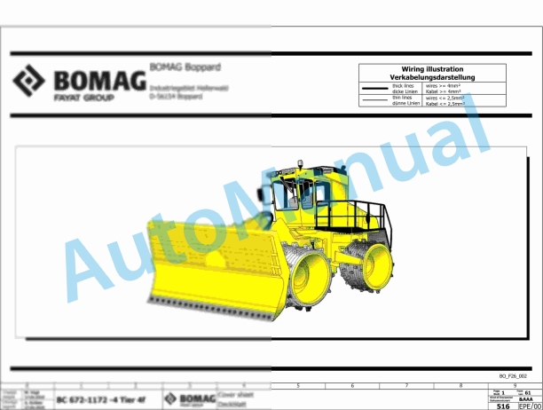
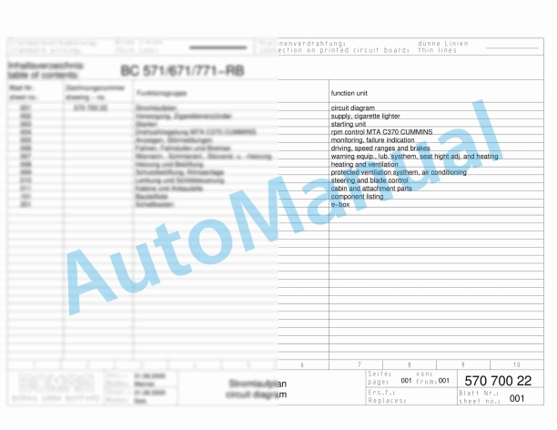
Bomag BC 571 RB Refuse Compactor Electric, Hydraulic Schematics Diagram 101570621033 – 101570621062

Bomag Service Manual PDF
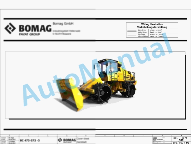
Bomag BC 463 RB-3 Refuse Compactor Electric Schematics Diagram 101930121001 – 101930129999
Bomag Service Manual PDF
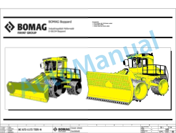
Bomag BC 472 RS Refuse Compactor Electric, Hydraulic Schematics Diagram 101930011002 – 101930011011

Bomag Service Manual PDF
Bomag Service Manual PDF
Bomag Service Manual PDF
Bomag BC 473 EB-3 Refuse Compactor Electric Schematics Diagram 101930151001 – 101930159999