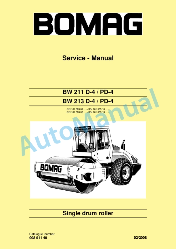
Bomag BW 211 D-4, BW 211 PD-4, BW 213 D-4, BW 213 PD-4 Single Drum Roller Service Manual 00891149
$30.00
- Type Of Manual: Service Manual
- Manual ID: 00891149
- Format: PDF
- Size: 89.3MB
- Number of Pages: 1046
- Serial Number:
10158309 and up
10158310 and up
10158308 and up
10158313 and up
-
Model List:
- BW 211 D-4 Single Drum Roller
- BW 211 PD-4 Single Drum Roller
- BW 213 D-4 Single Drum Roller
- BW 213 PD-4 Single Drum Roller
- 1. BW 211 D4 / PD4
- 2. BW 213 D4 / PD4
- 3. Single drum roller
- 4. Introduction
- 5. Safety regulations
- 6. General repair instructions
- 7. Tightening torques
- 8. General notes on maintenance
- 9. Table of fuels and lubricants
- 10. Runningin instructions
- 11. Maintenance chart
- 12. Special tools, tests and adjustments
- 13. Checking the rotation speeds
- 14. Checking / adjusting the neutral positions of the travel pump
- 15. Pressure tests in the travel circuit
- 16. Checking / adjusting the vibrator shaft speeds
- 17. Pressure measurements in the vibration circuit
- 18. Check the leakage rate of the vibration motor
- 19. Pressure test in steering circuit
- 20. Special tools for flushing
- 21. Flushing general
- 22. Flushing schematic travel circuit (distribution travel pump)
- 23. Flushing the travel circuit (travel pump distribution)
- 24. Flushing schematic travel circuit (distribution axle motor)
- 25. Flushing the travel circuit (axle motor distribution)
- 26. Flushing schematic for vibration drive
- 27. Flushing the vibration circuit
- 28. Bleeding the travel circuit
- 29. Bleeding the vibration circuit
- 30. BEM, BOMAG Evibmeter
- 31. Electrics module A68
- 32. Electric module K04
- 33. Heating/air conditioning control
- 34. Speedometer module
- 35. Service Training
- 36. Diesel engine
- 37. Fuel filter and check valve
- 38. Check, clean the water separator
- 39. Change the fuel prefilter cartridge
- 40. Change the fuel filter cartridge
- 41. Oil pressure switch and low oil pressure circuitry
- 42. Changing engine oil and oil filter cartridges
- 43. Coolant temperature switch
- 44. Disassembling and assembling the coolant temperature switch
- 45. Removing and installing the thermostat
- 46. Checking the thermostat in disassembled state
- 47. Change the coolant
- 48. Checking the antifreeze concentration
- 49. Threephase generator
- 50. Checking / replacing the ribbed Vbelt
- 51. Boost fuel solenoid valve
- 52. Engine shutdown solenoid
- 53. Air filter, differential pressure switch
- 54. Combustion air filter service
- 55. Heating flange on engine
- 56. Checking the heating flange control
- 57. Electric throttle control
- 58. Crankcase disassembling and assembling the ventilation valve
- 59. Disassembling and assembling the starter
- 60. Engine monitoring
- 61. Adjusting the valve clearance
- 62. Adjusting the control piston play
- 63. Checking the compression
- 64. Special tools, Deutz engine (TCD 2013 2V)
- 65. Physical basics
- 66. Refrigerant R134a
- 67. Compressor oil / refrigeration oil
- 68. Working principle of the air conditioning system
- 69. Monitoring devices
- 70. Description of components
- 71. Checking the compressor oil level
- 72. Checking the magnetic clutch
- 73. Inspection and maintenance work
- 74. Checking, replacing the refrigerant compressor Vbelt
- 75. Service the air conditioning
- 76. Drying and evacuation
- 77. Emptying in case of repair
- 78. Leak test
- 79. Filling instructions
- 80. Trouble shooting in refrigerant circuit, basic principles
- 81. Trouble shooting, refrigerant circuit diagram
- 82. Trouble shooting procedure
- 83. Steam table for R134a
- 84. Special tools, drum, single drum rollers
- 85. Repair overview for drum
- 86. Removing and installing the drum
- 87. Repairing the drum
- 88. Dismantling, assembling the change over weights
- 89. Changing the rubber buffers and adjusting the pretension
- 90. Special tools, oscillating articulated joint (BW177 to BW 216)
- 91. Repair overview oscillating articulated joint
- 92. Removing and installing the oscillating articulated joint
- 93. Dismantling the oscillating articulated joint
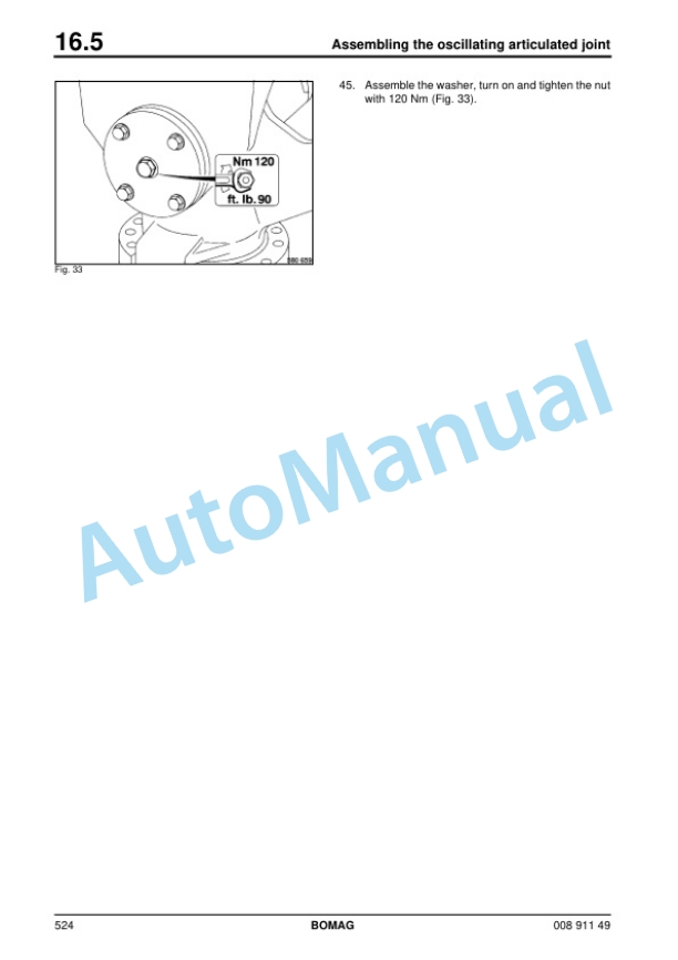
- 94. Assembling the oscillating articulated joint
- 95. Travel pump
- 96. Vibration pump
- 97. Drum drive
- 98. Vibration motor
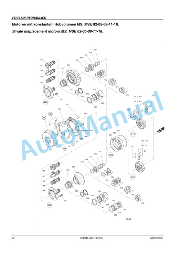
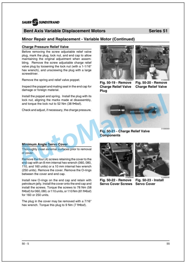
- 99. Axle drive motor
- 100. Axle
- 101. Hydraulic diagram 581 202 03
- 102. Wiring diagram 582 702 09
- 103. Wiring diagram 582 702 29
- 104. Wiring diagram 582 702 41
Bomag Service Manual PDF
Bomag BC 462 EB Refuse Compactor Electric, Hydraulic Schematics Diagram 101930021001 – 101930021018
Bomag Service Manual PDF
Bomag BC 463 RB-3 Refuse Compactor Electric Schematics Diagram 101930121001 – 101930129999
Bomag Service Manual PDF
Bomag BC 462 RB Refuse Compactor Electric, Hydraulic Schematics Diagram 101930071001 – 101930071002
Bomag Service Manual PDF
Bomag Service Manual PDF
Bomag BC 462 EB Refuse Compactor Electric, Hydraulic Schematics Diagram 101930061001 – 101930061001
Bomag Service Manual PDF
Bomag Service Manual PDF
Bomag Service Manual PDF
Bomag BC 571 RB Refuse Compactor Electric, Hydraulic Schematics Diagram 101570621033 – 101570621062
Bomag Service Manual PDF
Bomag Service Manual PDF
Bomag BC 462 RB Refuse Compactor Electric, Hydraulic Schematics Diagram 101930031001 – 101930031042

