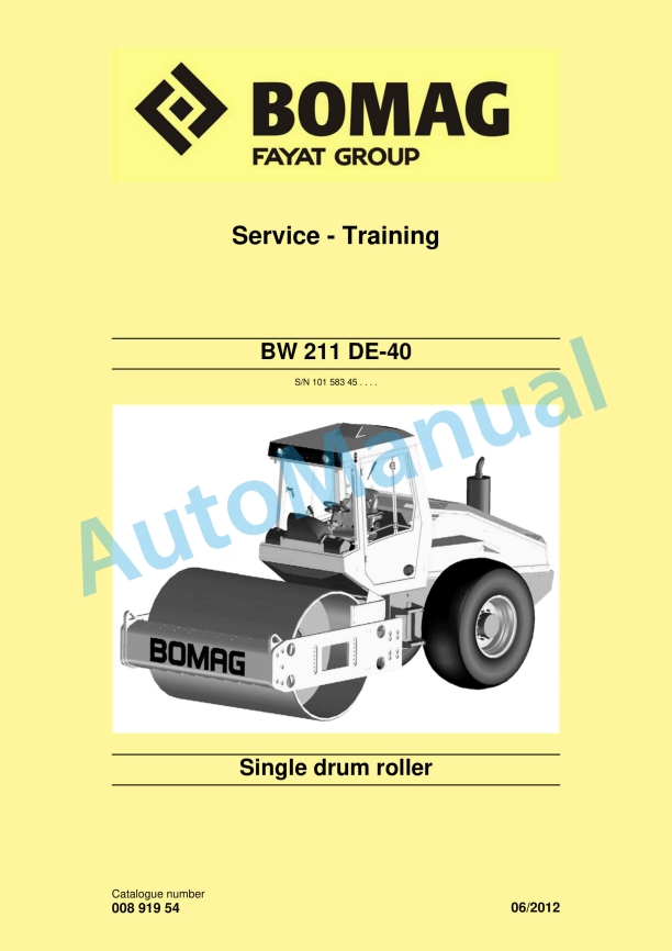
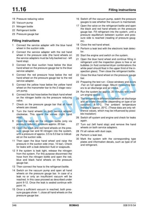
Bomag BW 211 DE-40 Single Drum Roller Service Training 00891954
$30.00
- Type Of Manual: Service Training
- Manual ID: 00891954
- Format: PDF
- Size: 19.3MB
- Number of Pages: 432
- Serial Number:
10158345
Category: Bomag Service Manual PDF
-
Model List:
- BW 211 DE-40 Single Drum Roller
- 1. BW 211 DE40
- 1.1. BW 211 DE40
- 2.
- 2.1.
- 3. General
- 3.1. General
- 3.2. Introduction
- 3.3. General
- 3.4. General
- 3.5. Transport work with cranes and lifting tackle
- 3.6. Precautions and codes of conduct for welding work
- 3.7. Operation of highvoltage systems
- 3.8. Old oils
- 3.9. Hydraulics
- 3.10. Hot fuels
- 3.11. Synthetic rubber
- 3.12. Poisonous substances
- 3.13. Air conditioning system
- 3.14. Battery
- 3.15. Special safety regulations
- 3.16. The values specified in the table apply for screws
- 3.17. The values specified in the table apply for screws
- 3.18. The values specified in the table apply for screws
- 3.19. The values specified in the table apply for screws
- 3.20. The values specified in the table apply for screws
- 3.21. The values specified in the table apply for screws
- 3.22. The values specified in the table apply for screws
- 3.23. The values specified in the table apply for screws
- 3.24. The values specified in the table apply for screws
- 3.25. The values specified in the table apply for screws
- 3.26. The values specified in the table apply for screws
- 3.27. The values specified in the table apply for screws
- 3.28. The values specified in the table apply for screws
- 3.29. The values specified in the table apply for screws
- 4. Technical data
- 4.1. Technical data
- 4.2.
- 4.3.
- 4.4.
- 5. Maintenance
- 5.1. Maintenance
- 5.2. General notes on maintenance
- 5.3. Fuels and lubricants
- 6. EPlan wiring diagrams
- 6.1. EPlan wiring diagrams
- 7. Electrics
- 7.1. Electrics
- 7.2. Service the battery
- 7.3. Service the battery
- 7.4. Service the battery
- 7.5. Service the battery
- 7.6. Service the battery
- 7.7. Service the battery
- 7.8. Service the battery
- 7.9. Service the battery
- 7.10. Service the battery
- 7.11.
- 7.12.
- 7.13. Starting with jump wires
- 7.14. Heating flange on engine
- 7.15. Heating flange on engine
- 7.16. Heating flange on engine
- 7.17.
- 7.18.
- 7.19.
- 7.20.
- 7.21.
- 7.22. S00, start switch
- 7.23.
- 7.24.
- 7.25.
- 7.26.
- 7.27.
- 7.28.
- 7.29.
- 8. Electronic modules
- 8.1. Electronic modules
- 8.2.
- 8.3.
- 8.4.
- 8.5.
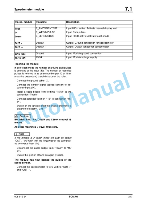
- 9. Speedometer Module
- 9.1. Speedometer Module
- 10. Hydraulics
- 10.1. Hydraulics
- 10.2. Variable displacement pumps, 90R055 and 90R075
- 10.3. Variable displacement pumps, 90R055 and 90R075
- 10.4. Variable displacement pumps, 90R055 and 90R075
- 10.5. Variable displacement pumps, 90R055 and 90R075
- 10.6. Variable displacement pump, 42R 041
- 10.7. Variable displacement pump, 42R 041
- 10.8. Swash plate principle, pump
- 10.9. Swash plate principle, pump
- 10.10. Swash plate motor with variable displacement, series 51
- 10.11. Swash plate motor with variable displacement, series 51
- 10.12. Functional principle radial piston motors, MS/MSE without brake
- 10.13. Functional principle radial piston motors, MS/MSE without brake
- 10.14. Vibration motor
- 10.15. Vibration motor
- 10.16. Swash plate principle, motor
- 10.17. Swash plate principle, motor
- 10.18. External gear pumps
- 10.19. External gear pumps
- 10.20. Brake control
- 10.21. Stopping the machine, operating the parking brake
- 10.22. Towing in case of an engine failure
- 10.23. Adjust the parking brake
- 10.24. Articulated joint
- 10.25. Check the hydraulic oil level
- 10.26. Changing hydraulic oil and breather filter
- 10.27. Changing the hydraulic oil filter
- 11. Tests and adjustments
- 11.1. Tests and adjustments
- 11.2. Checking the rotation speeds
- 11.3. Checking the rotation speeds
- 11.4. Checking / adjusting the neutral positions of the travel pump
- 11.5. Pressure tests in the travel circuit
- 11.6. Checking / adjusting the vibrator shaft speeds
- 11.7. Pressure measurements in the vibration circuit
- 11.8. Check the leakage rate of the vibration motor
- 11.9. Pressure test in steering circuit
- 12. Flushing and bleeding
- 12.1. Flushing and bleeding
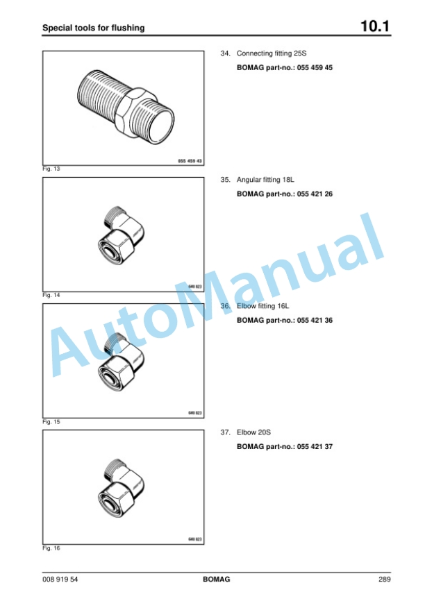
- 12.2. Special tools for flushing
- 12.3. Bleeding the vibration circuit
- 12.4. Bleeding the vibration circuit
- 12.5. Bleeding the vibration circuit
- 13. Air conditioning system
- 13.1. Air conditioning system
- 13.2. Checking, replacing the refrigerant compressor Vbelt
- 13.3. Checking, replacing the refrigerant compressor Vbelt
- 13.4. Checking, replacing the refrigerant compressor Vbelt
- 13.5. Checking, replacing the refrigerant compressor Vbelt
- 13.6. Air conditioning
- 13.7. Service the air conditioning
- 14. Drum
- 14.1. Drum
- 15. Circuit diagrams
- 15.1. Circuit diagrams
- 15.4. S/N Wiring diagram 9
- 15.5. S/N Wiring diagram 9
- 15.6. S/N Wiring diagram 9
- 15.7. S/N Wiring diagram 9
- 15.8. S/N Wiring diagram 9
- 15.9. S/N Wiring diagram 9
- 16.
- 16.1.
Rate this product
You may also like
Bomag Service Manual PDF
$30.00
Bomag Service Manual PDF
$30.00
Bomag Service Manual PDF
Bomag BC 572 RB Refuse Compactor Electric, Hydraulic Schematics Diagram 101570631001 – 101570631163
$30.00
Bomag Service Manual PDF
$30.00
Bomag Service Manual PDF
$30.00
Bomag Service Manual PDF
Bomag BC 462 EB Refuse Compactor Electric, Hydraulic Schematics Diagram 101930021001 – 101930021018
$30.00
Bomag Service Manual PDF
Bomag BC 462 EB Refuse Compactor Electric, Hydraulic Schematics Diagram 101930061001 – 101930061001
$30.00
Bomag Service Manual PDF
$30.00
Bomag Service Manual PDF
$30.00
Bomag Service Manual PDF
$30.00

