


Bomag BW 219 DH-4, BW 219 PDH-4, BW 226 DH-4, BW 226 PDH-4 Single Drum Roller Service Manual 00891693
$30.00
- Type Of Manual: Service Manual
- Manual ID: 00891693
- Format: PDF
- Size: 69.0MB
- Number of Pages: 1324
- Serial Number:
101582771516 and up
101582781035 and up
101582881035 and up
101582891009 and up
10158404, 10158405, 10158406, 10158407
Bomag Service Manual PDF
Bomag BC 462 RB Refuse Compactor Electric, Hydraulic Schematics Diagram 101930071001 – 101930071002
Bomag Service Manual PDF
Bomag Service Manual PDF
Bomag BC 472 RB Refuse Compactor Electric, Hydraulic Schematics Diagram 101930001002 – 101930001058
Bomag Service Manual PDF
Bomag BC 473 RB-3 Refuse Compactor Electric Schematics Diagram 101930131001 – 101930139999
Bomag Service Manual PDF
Bomag Service Manual PDF
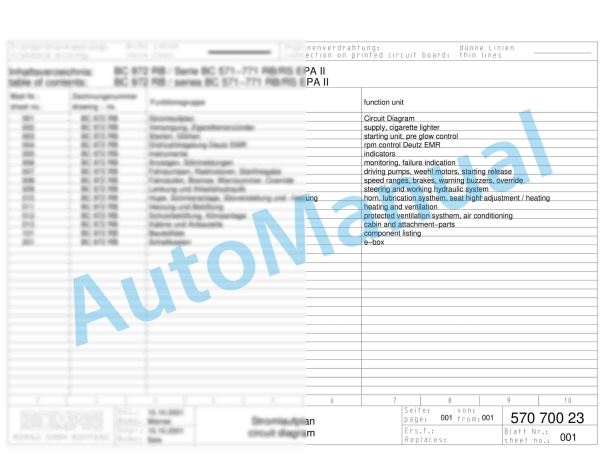
Bomag BC 572 RB Refuse Compactor Electric, Hydraulic Schematics Diagram 101570631001 – 101570631163

Bomag Service Manual PDF
Bomag BC 463 RB-3 Refuse Compactor Electric Schematics Diagram 101930121001 – 101930129999
Bomag Service Manual PDF
Bomag BC 473 EB-4 Refuse Compactor Electric Schematics Diagram 101930111001 – 101930119999
Bomag Service Manual PDF

Bomag Service Manual PDF
Bomag BC 472 RS Refuse Compactor Electric, Hydraulic Schematics Diagram 101930011002 – 101930011011