


Bomag BW 219 DH-5, BW 219 PDH-5, BW 226 DH-5, BW 226 PDH-5 Single Drum Roller Service Manual 00840076
$30.00
- Type Of Manual: Service Manual
- Manual ID: 00840076
- Format: PDF
- Size: 71.1MB
- Number of Pages: 1026
- Serial Number:
101586331001 and up
101586371001 and up
101586401001 and up
101586421001 and up

Bomag Service Manual PDF
Bomag BC 472 RS Refuse Compactor Electric, Hydraulic Schematics Diagram 101930011002 – 101930011011
Bomag Service Manual PDF
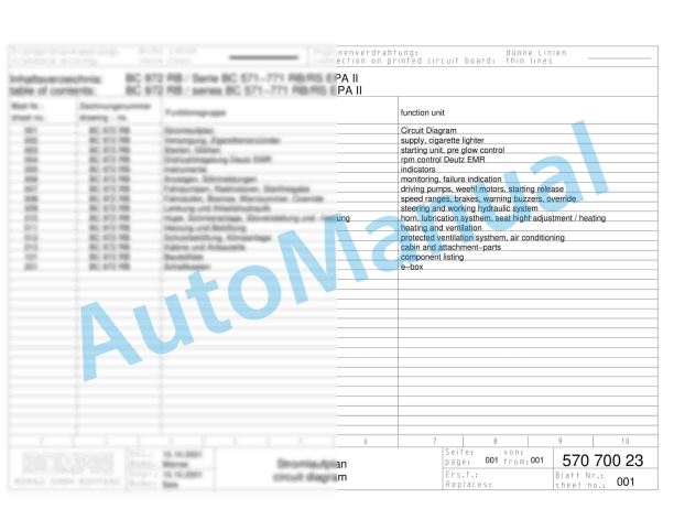
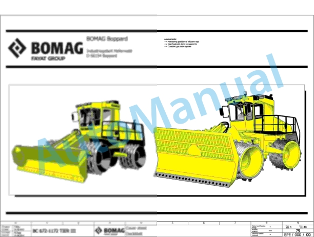
Bomag BC 572 RB Refuse Compactor Electric, Hydraulic Schematics Diagram 101570631001 – 101570631163
Bomag Service Manual PDF
Bomag BC 472 RS Refuse Compactor Electric, Hydraulic Schematics Diagram 101930051001 – 101930051010
Bomag Service Manual PDF

Bomag Service Manual PDF
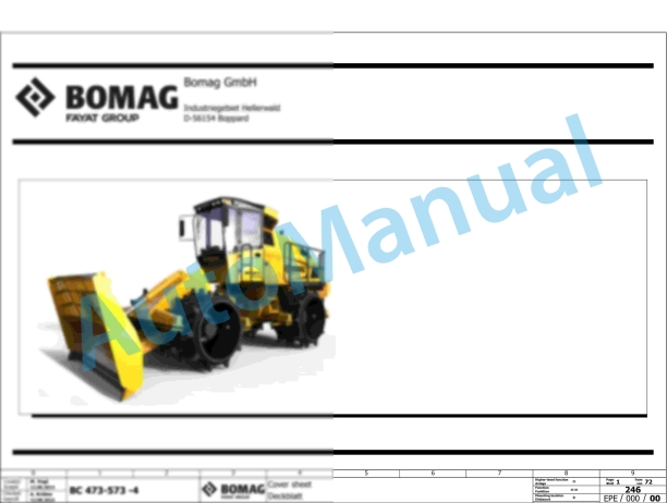
Bomag BC 473 RB-3 Refuse Compactor Electric Schematics Diagram 101930131001 – 101930139999
Bomag Service Manual PDF
Bomag Service Manual PDF
Bomag Service Manual PDF
Bomag Service Manual PDF
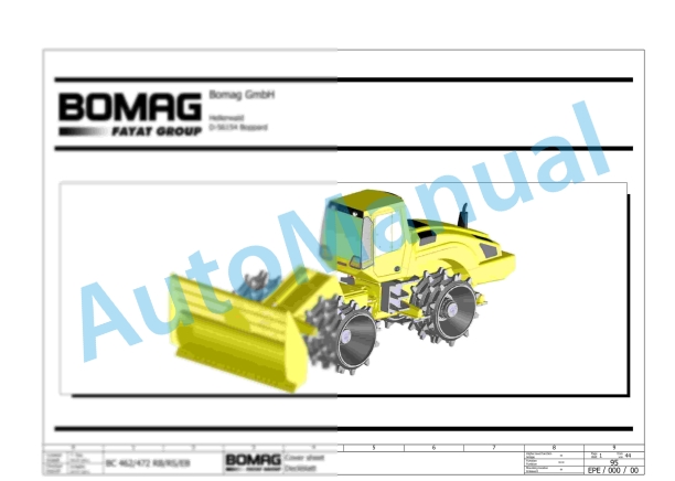
Bomag BC 462 RB Refuse Compactor Electric, Hydraulic Schematics Diagram 101930071001 – 101930071002

Bomag Service Manual PDF