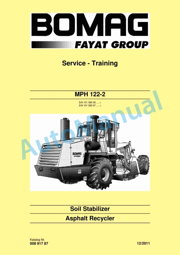
Bomag MPH 122-2 Soil Stabilizer Service Training 00891787
$30.00
- Type Of Manual: Service Training
- Manual ID: 00891787
- Format: PDF
- Size: 45.5MB
- Number of Pages: 658
- Serial Number:
10159006 and up
10159007 and up
-
Model List:
- MPH 122-2 Soil Stabilizer
- 1. MPH 1222
- 1.1. MPH 1222
- 2. General
- 2.1. General
- 2.2. Introduction
- 2.3. General
- 2.4. General
- 2.5. Transport work with cranes and lifting tackle
- 2.6. Precautions and codes of conduct for welding work
- 2.7. Operation of highvoltage systems
- 2.8. Old oils
- 2.9. Hydraulics
- 2.10. Hot fuels
- 2.11. Synthetic rubber
- 2.12. Poisonous substances
- 2.13. Air conditioning system
- 2.14. Battery
- 2.15. Special safety regulations
- 2.16. The values specified in the table apply for screws
- 2.17. The values specified in the table apply for screws
- 2.18. The values specified in the table apply for screws
- 2.19. The values specified in the table apply for screws
- 2.20. The values specified in the table apply for screws
- 2.21. The values specified in the table apply for screws
- 2.22. The values specified in the table apply for screws
- 2.23. The values specified in the table apply for screws
- 2.24. The values specified in the table apply for screws
- 2.25. The values specified in the table apply for screws
- 2.26. The values specified in the table apply for screws
- 2.27. The values specified in the table apply for screws
- 2.28. The values specified in the table apply for screws
- 2.29. The values specified in the table apply for screws
- 3. BOMAG Stabilizer / Recycler
- 3.1. BOMAG Stabilizer / Recycler
- 4. Technical data
- 4.1. Technical data
- 4.2.
- 4.3.
- 4.4.
- 5. Maintenance
- 5.1. Maintenance
- 5.2. General notes on maintenance
- 5.3. Fuels and lubricants
- 5.4. Coolant
- 5.5. Mineral oil based hydraulic oil
- 5.6. Biodegradable hydraulic oil
- 5.7. Gear oil
- 5.8. Milling gear oil
- 5.9. Lubrication grease
- 5.10. Thermal oil
- 5.11. Compressor service unit
- 6. EPlan wiring diagrams
- 6.1. EPlan wiring diagrams
- 7. Electrics
- 7.1. Electrics
- 7.2. Battery service, checking the main battery switch
- 7.3. Battery service, checking the main battery switch
- 7.4. Battery service, checking the main battery switch
- 7.5. Battery service, checking the main battery switch
- 7.6. Starting with jump wires
- 7.7.
- 7.8.
- 7.9.
- 7.10.
- 7.11.
- 7.12.
- 7.13.
- 7.14.
- 7.15.
- 7.16.
- 7.17.
- 7.18.
- 8. Electronic control
- 8.1. Electronic control
- 9. Engine electrics
- 9.1. Engine electrics
- 10. Engine
- 10.1. Engine
- 10.2. Check, adjust the valve clearance
- 10.3. Check, adjust the valve clearance
- 10.4. Check, adjust the valve clearance
- 10.5. Check, adjust the valve clearance
- 10.6. Check, adjust the valve clearance
- 10.7. Check, adjust the valve clearance
- 10.8. Check, adjust the valve clearance
- 10.9. Check, adjust the valve clearance
- 10.10. Check, adjust the valve clearance
- 10.11. Checking the engine oil level
- 10.12. Changing engine oil and oil filter cartridge
- 10.13. Check the coolant level
- 10.14. Checking the condition of the coolant
- 10.15. Checking/changing the coolant
- 10.16. Check, clean the water separator
- 10.17. Changing the fuel filter
- 10.18. Replacing the fuel prefilter cartridge, bleed the fuel system
- 10.19. Cleaning, changing the dry air filter cartridge
- 10.20. Servicing the generator Vbelt
- 10.21. Check the engine mounts
- 10.22. Check the fastening of engine / turbocharger / combustion air hoses
- 10.23. Cleaning the intercooler
- 10.24. Intercooler, draining off oil/ condensation water
- 10.25. Checking the crankcase pressure
- 10.26. Replacing the crankcase ventilation valve
- 11. Air conditioning system
- 11.1. Air conditioning system
- 11.2. Servicing the air conditioning compressor
- 11.3. Servicing the air conditioning compressor
- 11.4. Servicing the air conditioning compressor
- 11.5. Servicing the air conditioning compressor
- 11.6. Service the air conditioning
- 12. Hydraulics
- 12.1. Hydraulics
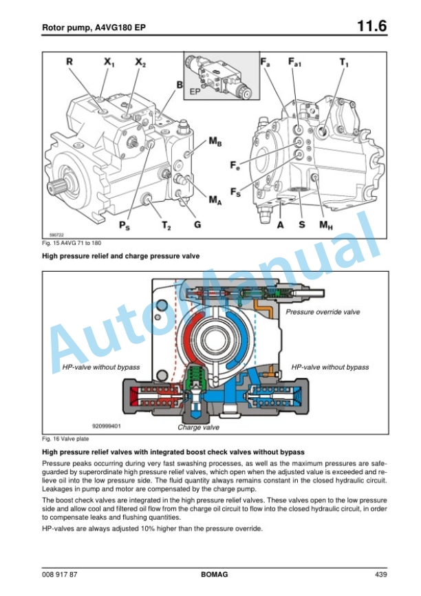
- 12.2. Variable displacement pumps, A4VG28EP to A4VG180EP
- 12.3. Variable displacement pumps, A4VG28EP to A4VG180EP
- 12.4. Variable displacement pumps, A4VG28EP to A4VG180EP
- 12.5. Variable displacement pumps, A4VG28EP to A4VG180EP
- 12.6. Swash plate principle
- 12.7. Swash plate principle
- 12.8. External gear pumps
- 12.9. External gear pumps
- 12.10. Multiple gear pumps
- 12.11. Description of function
- 12.12.
- 12.13.
- 12.14. Function logic of the rotor drive
- 12.15. Plugin fixed displacement motors A2FE and A2FM
- 12.16. OSP steering valve
- 12.17. OSP steering valve
- 12.18. Control valve blocks SP08
- 12.19. Control valve blocks SP08
- 12.20. Raising/lowering the cabin
- 12.21. Raising/lowering the cabin
- 12.22. Towing
- 12.23. External gear motors
- 12.24. External gear motors
- 12.25. way flow control valve, adjustable
- 12.26. Cleaning the intercooler
- 12.27. Checking the hydraulic oil level
- 12.28. Changing hydraulic oil and breather filter
- 12.29. Checking the contamination of the hydraulic oil filters
- 12.30. Change the hydraulic oil fine filter
- 13. Water injection
- 13.1. Water injection
- 13.2.
- 13.3. External gear motors
- 13.4. External gear motors
- 13.5. External gear motors
- 13.6. Water dosing system
- 13.7. Water sprinkler system, maintenance in the event of frost
- 14. Bitumen dosing system
- 14.1. Bitumen dosing system
- 14.2.
- 14.3.
- 14.4.
- 14.5.
- 14.6.
- 14.7.
- 14.8.
- 14.9.
- 14.10.
- 14.11. Checking the reaction water level
- 14.12. Checking the reaction water level
- 14.13. Checking the reaction water level
- 14.14. Reaction water tank
- 14.15. Checking the oil level for the reaction water pump
- 14.16. Checking the oil level in compressor and service unit
- 14.17. Checking the thermal oil
- 14.18. Checking the contamination of the hydraulic oil filters
- 14.19. Checking the binder pump
- 14.20. Checking the spraying sections
- 14.21. Checking, cleaning the additional fuel filter
- 14.22. Change the additional fuel filter
- 14.23. Changing the thermal oil
- 14.24. Compressor oil change
- 14.25. Cleaning the bitumen filter
- 15. Circuit diagrams
- 15.1. Circuit diagrams
- 15.2. S/N Wiring diagram 42
- 15.3. S/N Wiring diagram 42
- 15.4. S/N Wiring diagram 42
- 15.5. S/N Wiring diagram 42
- 15.6. S/N Wiring diagram 42
- 15.7. S/N Wiring diagram 42
- 15.8. S/N Wiring diagram 42
- 15.9. S/N Wiring diagram 42
Bomag Service Manual PDF
Bomag Service Manual PDF
Bomag BC 472 RB Refuse Compactor Electric, Hydraulic Schematics Diagram 101930041001 – 101930041022
Bomag Service Manual PDF
Bomag Service Manual PDF
Bomag Service Manual PDF
Bomag BC 463 RB-3 Refuse Compactor Electric Schematics Diagram 101930121001 – 101930129999
Bomag Service Manual PDF
Bomag BC 472 RB Refuse Compactor Electric, Hydraulic Schematics Diagram 101930001002 – 101930001058
Bomag Service Manual PDF
Bomag Service Manual PDF
Bomag BC 472 RS Refuse Compactor Electric, Hydraulic Schematics Diagram 101930011002 – 101930011011
Bomag Service Manual PDF
Bomag BC 462 RB Refuse Compactor Electric, Hydraulic Schematics Diagram 101930031001 – 101930031042
Bomag Service Manual PDF
Bomag BC 462 EB Refuse Compactor Electric, Hydraulic Schematics Diagram 101930021001 – 101930021018

