Claas Ares 735 725 720 715 710 Rz (T97) Tractors Operator Manual EN
$50.00
- Model: Ares 735 725 720 715 710 Rz (T97) Tractors
- Type Of Manual: Operator Manual
- Language: EN
- Format: PDF(s)
- Size: 51.1 MB
File List:
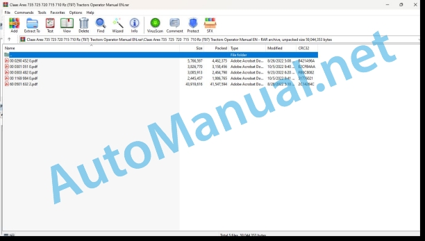
00 0290 452 0.pdf
00 0301 051 0.pdf
00 0303 482 0.pdf
00 1169 984 0.pdf
60 0501 632 2.pdf
00 0290 452 0.pdf:
Contents
1 Introduction
1.1 General Information
1.1.1 How to use this manual
1.1.2 Validity of manual
1.1.3 Specifications
1.1.4 Licensing for road traffic
1.2 Various components / Machine body
1.2.1 Spare parts and technical questions
1.2.2 GPS PILOT monitor identification plate
1.2.3 Base station identification plate
2 Safety
2.1 General Information
2.1.1 General information
2.1.2 Important information
2.1.3 Intended use
2.1.4 Accumulators
2.2 Safety rules
2.2.1 Identification of warning and danger signs
3 Sectional view of machine
3.1 Antennas – Overview
3.1.1 GPS antenna (BASELINE HD, SBAS)
3.1.2 Antenna (BASELINE HD)
3.1.3 GPS antenna (OMNISTAR HP, RTK)
3.1.4 Antenna (RTK)
3.2 Signal overview
3.2.1 GPS PILOT SBAS
3.2.2 GPS PILOT OMNISTAR
3.2.3 GPS PILOT BASELINE HD
3.2.4 GPS PILOT RTK
3.3 GPS PILOT monitor
3.3.1 Connections at the rear of the GPS PILOT monitor
3.3.2 Connections on the left of the GPS PILOT monitor
3.4 Base station for BASELINE HD
3.4.1 Base station
3.4.2 Charger (up to serial no. …)
3.4.3 Charger (from serial no. …)
3.4.4 Cable for external power supply
3.4.5 Cable for PC connection
4 Prior to initial operation
4.1 General Information
4.1.1 General warnings
4.2 Initial operation of base station
4.2.1 Base station initial operation check list
4.2.2 Making the charger (up to serial no. …) available
4.2.3 Making the charger (from serial no. …) available
4.2.4 Charging the base station battery
4.2.5 Switching on the base station
4.2.6 Supplying the base station with an external battery
4.2.7 Changing the base station frequency
4.3 GPS antenna initial operation (OMNISTAR HP, RTK)
4.3.1 Check list for initial operation of GPS antenna (OMNISTAR HP, RTK)
4.3.2 Having the GPS antenna enabled (OMNISTAR HP, RTK)
4.4 Initial operation of GPS PILOT monitor
4.4.1 Check list for initial operation of GPS PILOT monitor
4.5 Initial operation
4.5.1 LEXION initial operation check list
4.5.2 COUGAR initial operation check list
4.5.3 XERION initial operation check list
4.5.4 Tractor initial operation check list
5 Prior to each operation
5.1 General Information
5.1.1 General warnings
5.1.2 Preparing fieldwork with the GPS PILOT
6 GPS PILOT operation
6.1 General Information
6.1.1 General warnings
6.2 Settings and displays
6.2.1 Layout conventions of buttons and displays
6.2.2 Overview of buttons
6.2.3 Start screen
6.3 Operation of screen menus
6.3.1 Basic settings
6.3.2 GPS status information
6.3.3 Steering settings
6.3.4 Machine settings
6.3.5 Job management
6.3.6 Field view
6.3.7 Function buttons in the screen menus
7 GPS PILOT fieldwork
7.1 General Information
7.1.1 General warnings
7.2 Base station
7.2.1 Setting up the base station
7.2.2 Switching on the base station
7.2.3 Setting the frequency with BASELINE HD
7.3 LEXION
7.3.1 Learning the ATP front attachment zero point
7.3.2 Selecting the AUTOPILOT signal (from CEBIS version 8.2)
7.3.3 Learning the steering zero point
7.3.4 Switching on the AUTO PILOT
7.3.5 Switching off the AUTO PILOT
7.4 COUGAR
7.4.1 Enabling the AUTO PILOT
7.4.2 Selecting the AUTO PILOT signal
7.4.3 Switching on the AUTO PILOT
7.4.4 Switching off the AUTO PILOT
7.5 XERION
7.5.1 Enabling the AUTO PILOT
7.5.2 Selecting the AUTO PILOT signal
7.5.3 Switching on the AUTO PILOT
7.5.4 Switching off the AUTO PILOT
7.6 Tractor
7.6.1 Switching the eDrive box on / off
7.6.2 Switching on the AUTO PILOT
7.6.3 Switching off the AUTO PILOT
7.6.4 Basic settings
7.6.5 Entering the antenna height
7.6.6 Calibrating the inclination sensor
7.6.7 Setting the steering adjustment.
7.6.8 Adjusting the steering speed
7.7 Performing fieldwork with the GPS PILOT
7.7.1 Types of field drives
7.7.2 Activate straight guidance.
7.7.3 Activating contour guidance
7.7.4 Activating circular guidance
7.7.5 Relocating A=B lines in the A=B mode
8 Maintenance
8.1 General Information
8.1.1 General warnings
8.2 Electric system / Electronics
8.2.1 Battery
8.2.2 Removing / installing the base station battery
00 0301 051 0.pdf:
PROFI CAM 3
Table of contents
1 Introduction
1.1 Notes on the manual
1.1.1 Validity of manual
1.1.2 Information about this Operator’s Manual
1.1.3 Symbols and notes
1.1.4 Optional equipment
1.1.5 Qualified specialist workshop
1.1.6 Maintenance information
1.1.7 Warranty notes
1.1.8 Spare parts and technical questions
1.2 Intended use
1.2.1 Intended use
1.2.2 Reasonably foreseeable misuse
2 Safety
2.1 Identifying warnings
2.1.1 Hazard signs
2.1.2 Signal word
2.2 Safety rules
2.2.1 Meaning of Operator’s Manual
2.2.2 Observing safety decals and warnings
2.2.3 Optional equipment and spare parts
3 Product description
3.1 Overview and method of operation
3.1.1 How the PROFI CAM works
3.2 Identification plates and identification number
3.2.1 Position of identification plates
3.2.2 Explanation of PROFI CAM identification plate
3.3 Information on the product
3.3.1 CE marking
4 Operating and control elements
4.1 Camera system
4.1.1 Camera system monitor
4.2 Menu structure
4.2.1 Main menu
4.2.2
4.2.3
4.2.4
4.2.5
4.2.6
5 Technical specifications
5.1 PROFI CAM
5.1.1 Monitor
5.1.2 Camera
5.1.3 Switch box
5.1.4 Degree of protection against foreign bodies and water
6 Preparing the product
6.1 Shutting down and securing the machine
6.1.1 Switching off and securing the machine
6.2 Prior to operation
6.2.1 Carry out prior to operation
6.2.2 Installing the sun protection
6.2.3 Aligning the camera
6.2.4 Connecting the camera electrics
7 Operation
7.1 Monitor
7.1.1 Switching on the monitor
7.1.2 Calling up the menu
7.1.3 Setting a menu item
7.1.4 Setting the image orientation
7.1.5 Setting automatic screen darkening
7.1.6 Image mirroring
7.1.7 Setting the trigger view
7.1.8 Setting the follow-up time for trigger view
7.1.9 Setting the display mode
7.1.10 Activating/deactivating a display mode
8 Faults and remedies
8.1 Electrical and electronic system
8.1.1 Overview of problems on PROFI CAM camera system
8.1.2 Replacing the switch box fuse
9 Maintenance
9.1 Maintenance intervals
9.1.1 Every 10 operating hours or daily
9.2 Camera system
9.2.1 Checking the camera system for dirt
9.2.2 Cleaning the camera
9.2.3 Cleaning the switch box
9.2.4 Cleaning the monitor
10 Placing out of operation and disposal
10.1 General Information
10.1.1 Putting out of operation and disposal
11 Technical terms and abbreviations
11.1 Abbreviations
11.1.1 Units
11.1.2 Abbreviations
11.1.3 Technical terms
00 0303 482 0.pdf:
PROFI CAM 4
Table of contents
1 Introduction
1.1 Notes on the manual
1.1.1 Validity of manual
1.1.2 Information about this Operator’s Manual
1.1.3 Symbols and notes
1.1.4 Optional equipment
1.1.5 Qualified specialist workshop
1.1.6 Maintenance information
1.1.7 Notes on warranty
1.1.8 Spare parts and technical questions
1.2 Intended use
1.2.1 Intended use
1.2.2 Reasonably foreseeable misuse
2 Safety
2.1 Identifying warnings
2.1.1 Hazard signs
2.1.2 Signal word
2.2 Safety rules
2.2.1 Meaning of Operator’s Manual
2.2.2 Structural changes
2.2.3 Optional equipment and spare parts
2.2.4 Operation only following proper putting into operation
2.2.5 Technical status
2.2.6 Respecting technical limit values
Respecting technical limit values
2.2.7 Hazards when driving on roads and fields
3 Product description
3.1 Overview and method of operation
3.1.1 How the PROFI CAM works
3.2 Identification plates and identification number
3.2.1 Identification plates
3.3 Information on the product
3.3.1 CE marking
4 Operating and display elements
4.1 Camera system
4.1.1 Camera system monitor
4.1.2 CEBIS
4.2 Menu structure
4.2.1 Main menu
4.2.2
4.2.3
4.2.4
4.2.5
4.2.6
5 Technical specifications
5.1 PROFI CAM
5.1.1 Monitor
5.1.2 Camera
5.1.3 Switch box
6 Preparing the product
6.1 Switching off and securing the machine
6.1.1 Switching off and securing the machine
6.2 Prior to putting into operation
6.2.1 Carry out prior to operation
6.2.2 Installing the sun protection
6.2.3 Aligning the camera
7 Operation
7.1 Monitor
7.1.1 Switching on the monitor
7.1.2 Calling up the menu
7.1.3 Setting a menu item
7.1.4 Setting the image orientation
7.1.5 Setting automatic screen darkening
7.1.6 Image mirroring
7.1.7 Setting the trigger view
7.1.8 Setting the follow-up time for trigger view
7.1.9 Setting the display mode
7.1.10 Activating/deactivating a display mode
8 Faults and remedies
8.1 Electric and electronic system
8.1.1 Overview of problems on PROFI CAM camera system
9 Maintenance
9.1 Maintenance intervals
9.1.1 Every 10 operating hours or daily
9.2 Camera system
9.2.1 Checking the camera system for dirt
9.2.2 Cleaning the camera
9.2.3 Cleaning the switch box
9.2.4 Cleaning the monitor
10 Putting out of operation and disposal
10.1 General information
10.1.1 Putting out of operation and disposal
11 Technical terms and abbreviations
11.1 Abbreviations
11.1.1 Units
11.1.2 Abbreviations
11.1.3 Technical terms
00 1169 984 0.pdf:
Sensor case for tractors Stage IIIB, IV and VSensor case for tractors Stage IIIB, IV and VSensor case for Stage IIIB, IV and V tractors
Contents
1 Sensorkoffer – Sensor case – Sensor suitcase – Stage IIIB, IV & V
1.1 Auflistung Kofferinhalt
1.1 Listing case content
1.1 Presentation of the contents of the suitcase
60 0501 632 2.pdf:
6005016322-GB-version06.01156.pdf
Page – 2 –
Page – 3 –
Page – 4 –
Page – 5 –
Page – 6 –
Page – 7 –
Page – 8 –
Page – 9 –
Page – 10 –
Page – 11 –
Page – 12 –
Page – 13 –
Page – 14 –
Page – 15 –
Page – 16 –
Page – 17 –
Page – 18 –
Page – 19 –
Page – 20 –
Page – 21 –
Page – 22 –
Page – 23 –
Page – 24 –
Page – 25 –
Page – 26 –
Page – 27 –
Page – 28 –
Page – 29 –
Page – 30 –
Page – 31 –
Page – 32 –
Page – 33 –
Page – 34 –
Page – 35 –
Page – 36 –
Page – 37 –
Page – 38 –
Page – 39 –
Page – 40 –
Page – 41 –
Page – 42 –
Page – 43 –
Page – 44 –
Page – 45 –
Page – 46 –
Page – 47 –
Page – 48 –
Page – 49 –
Page – 50 –
Page – 51 –
Page – 52 –
Page – 53 –
Page – 54 –
Page – 55 –
Page – 56 –
Page – 57 –
Page – 58 –
Page – 59 –
Page – 60 –
Page – 61 –
Page – 62 –
Page – 63 –
Page – 64 –
Page – 65 –
Page – 66 –
Page – 67 –
Page – 68 –
Page – 69 –
Page – 70 –
Page – 71 –
Page – 72 –
Page – 73 –
Page – 74 –
Page – 75 –
Page – 76 –
Page – 77 –
Page – 78 –
Page – 79 –
Page – 80 –
Page – 81 –
Page – 82 –
Page – 83 –
Page – 84 –
Page – 85 –
Page – 86 –
Page – 87 –
Page – 88 –
Page – 89 –
Page – 90 –
Page – 91 –
Page – 92 –
Page – 93 –
Page – 94 –
Page – 95 –
Page – 96 –
Page – 97 –
Page – 98 –
Page – 99 –
Page – 100 –
Page – 101 –
Page – 102 –
Page – 103 –
Page – 104 –
Page – 105 –
Page – 106 –
Page – 107 –
Page – 108 –
Page – 109 –
Page – 110 –
Page – 111 –
Page – 112 –
Page – 113 –
Page – 114 –
Page – 115 –
Page – 116 –
Page – 117 –
Page – 118 –
Page – 119 –
Page – 120 –
Page – 121 –
Page – 122 –
Page – 123 –
Page – 124 –
Page – 125 –
Page – 126 –
Page – 127 –
Page – 128 –
Page – 129 –
Page – 130 –
Page – 131 –
Page – 132 –
Page – 133 –
Page – 134 –
Page – 135 –
Page – 136 –
Page – 137 –
Page – 138 –
Page – 139 –
Page – 140 –
Page – 141 –
Page – 142 –
Page – 143 –
Page – 144 –
Page – 145 –
Page – 146 –
Page – 147 –
Page – 148 –
Page – 149 –
Page – 150 –
Page – 151 –
Page – 152 –
Page – 153 –
Page – 154 –
Page – 155 –
Page – 156 –
Page – 157 –
Page – 158 –
Page – 159 –
Page – 160 –
Page – 161 –
Page – 162 –
Page – 163 –
Page – 164 –
Page – 165 –
Page – 166 –
Page – 167 –
Page – 168 –
Page – 169 –
Page – 170 –
Page – 171 –
Page – 172 –
Page – 173 –
Page – 174 –
Page – 175 –
Page – 176 –
Page – 177 –
Page – 178 –
Page – 179 –
Page – 180 –
Page – 181 –
Page – 182 –
Page – 183 –
Page – 184 –
Page – 185 –
Page – 186 –
Page – 187 –
Page – 188 –
Page – 189 –
Page – 190 –
Page – 191 –
Page – 192 –
Page – 193 –
Page – 194 –
Page – 195 –
Page – 196 –
Page – 197 –
Page – 198 –
Page – 199 –
Page – 200 –
Page – 201 –
Page – 202 –
Page – 203 –
Page – 204 –
Page – 205 –
Page – 206 –
Page – 207 –
Page – 208 –
Page – 209 –
Page – 210 –
Page – 211 –
Page – 212 –
Page – 213 –
Page – 214 –
Page – 215 –
Page – 216 –
Page – 217 –
Page – 218 –
Page – 219 –
Page – 220 –
Page – 221 –
Page – 222 –
Page – 223 –
Page – 224 –
Page – 225 –
Page – 226 –
Page – 227 –
Page – 228 –
Page – 229 –
John Deere Repair Technical Manual PDF
John Deere Repair Technical Manual PDF
John Deere Repair Technical Manual PDF
John Deere DF Series 150 and 250 Transmissions (ANALOG) Component Technical Manual CTM147 05JUN98
John Deere Repair Technical Manual PDF
John Deere Parts Catalog PDF
John Deere Tractors 7500 Parts Catalog CPCQ26568 30 Jan 02 Portuguese
John Deere Repair Technical Manual PDF
John Deere Repair Technical Manual PDF
New Holland Service Manual PDF
John Deere Repair Technical Manual PDF
John Deere Parts Catalog PDF
John Deere Tractors 6300, 6500, and 6600 Parts Catalog CQ26564 (29SET05) Portuguese


