Claas ARION 430-410 (A21) Tractor Repair Manual DE
$300.00
- Model: ARION 430-410 (A21) Tractor
- Type Of Manual: Repair Manual
- Language: DE
- Format: PDF(s)
- Size: 170 MB
File List:
– 00 1168 917 0.pdf
– Size(0.4 MB) 1.26.2010.pdf
– Size(0.6 MB) 10/11/2009.pdf
– Size(1.6 MB) 5.31.2010.pdf
– Size(1.8 MB) 10/11/2009.pdf
– Size(1.8 MB) 11.25.2009.pdf
– Size(10.1 MB) 4.24.2013.pdf
– Size(10.3 MB) 2.2.2010.pdf
– Size(2.3 MB) 10/11/2009.pdf
– Size(2.6 MB) 1.26.2010.pdf
– Size(24.8 MB) 2.23.2017.pdf
– Size(25.7 MB) 10.30.2012.pdf
– Size O 4.5 Fasteners and sealants
4.6 Symbols
4.7 General repair instructions
4.8 Tightening torques
4.9 Technical data
5 Security
5.1 Important
5.2 Labeling of warning and danger notices
5.3 General safety instructions and accident prevention regulations
5.4 First aid measures
5.5 Leaving the tractor
5.6 Adjustment and maintenance work
5.7 Risk of injury from hydraulic fluid
5.8 Air conditioning
5.9 Pressure accumulator
5.10 Battery disconnect switch
5.11 Jack up the tractor
5.12 Stopping the tractor
6 01 Motor
6.1 0102 Complete component
6.2 0110 Motor housing
6.3 0115 Motor Engine
6.4 0120 cylinder head / valves / distributor wheel
6.5 0125 Injection / Fuel System
6.6 0130 lubricating oil system
6.7 0135 cooling system
6.8 0140 exhaust system
7 02 Gearbox / clutch / cardan shaft
7.1 0202 Complete component
7.2 0210 Vibration damper
7.3 0218 Control / actuation clutch
7.4 0222 Hydraulic reversing
7.5 0230 Mechanical gears
7.6 0234 powershift transmission
7.7 0240 rear axle housing
7.8 0242 Differential
7.9 0252 Electro-hydraulic front axle drive
8 03 Chassis
8.1 0300 Chassis
8.2 0325 Front steering drive axle
9 04 Brake
9.1 0405 Service brake
9.2 0415 parking brake
9.3 0420 Compressed air trailer brake system
10 05 Steering
10.1 0505 Steering
11 06 Lifting device
11.1 0605 rear power lift
11.2 0610 Front power lift
11.3 0615 Front loader
12 08 Drives
12.1 0802 Rear PTO
12.2 0804 Front PTO
13 09 Hydraulics
13.1 0900 Hydraulics General
13.2 0910 Pumps
13.3 0920 Valves
14 12 Cab / Driver’s cab
14.1 1210 Cabin
14.2 1235 Cabin heater
14.3 1240 Air conditioning
Size(0.4 MB) 1.26.2010.pdf
Table of Content:
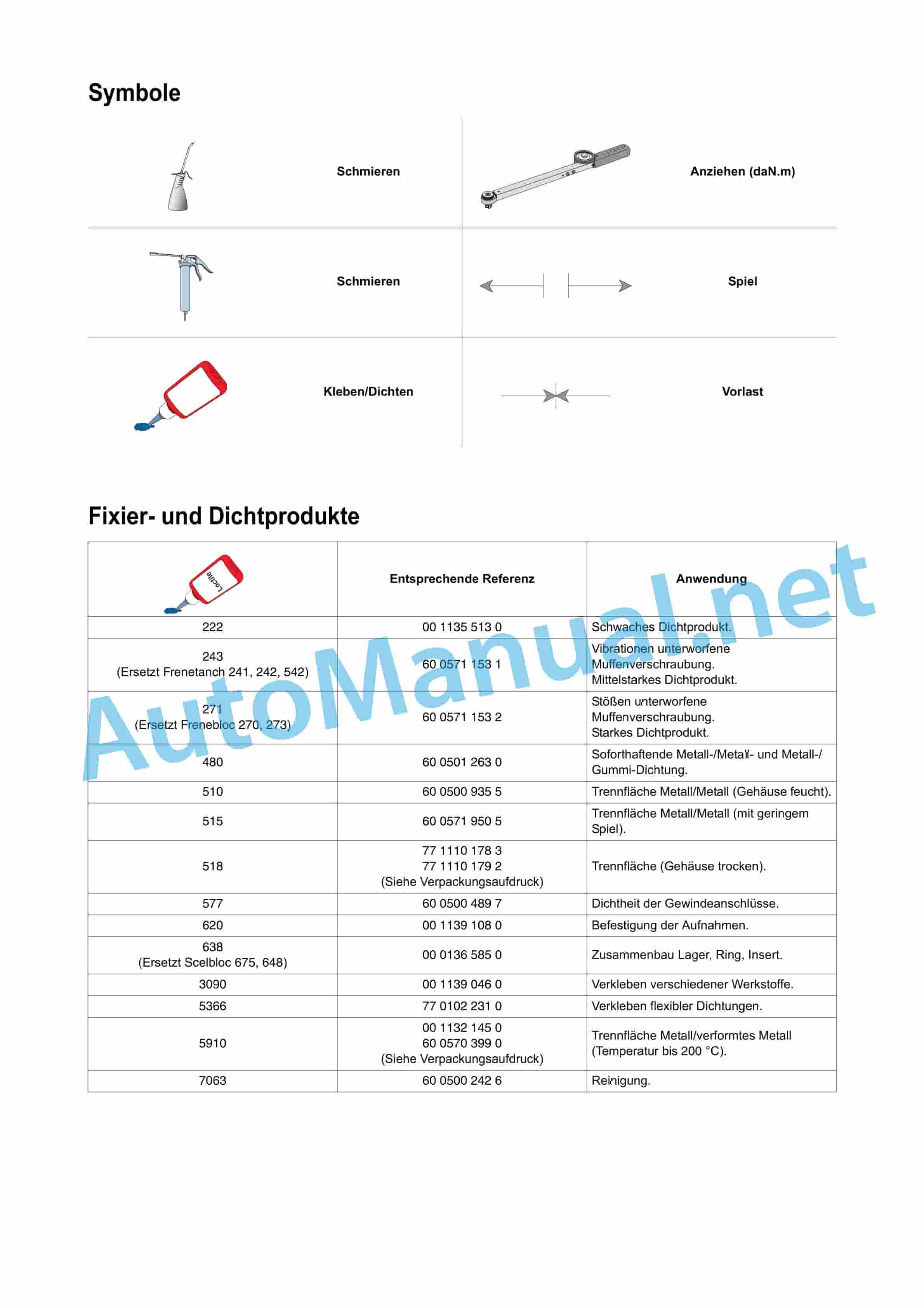
2 fixing and sealing products
3 compressed air lines
4 hydraulic lines
5 Standardized tightening torques (except specific tightening torques from technical support)
5.1 Screw class
5.2 Hydraulic connections standard DIN 3865
Size(0.6 MB) 10/11/2009.pdf
Table of Content:
1 03 Chassis
1.1 Front steering axle with drive wheels
Size(1.6 MB) 5.31.2010.pdf
Table of Content:
1 Error codes
1.1 Introduction
1.2 Display of error codes
1.3 Description of the error code list
1.4 List of error codes
Size(1.8 MB) 10/11/2009.pdf
Table of Content:
1 05 Steering
1.1 Setting
1.2 Specific torques and sealants
1.3 Measurements and controls 60 and 98 l/min
1c structure
3.2 Compressed air plan
3.3 Tightening torques
3.4 Measurements and controls
3.5 Data sheets
4 trailer oil pressure brake
4.1 Measurements and controls
4.2 Data sheets
Size(10.1 MB) 4.24.2013.pdf
Table of Content:
1 06 lifting device
1.1 Rear power lift 60 and 98 l/Min
1.2 Front power lift
1.3 Front loader
Size(10.3 MB) 2.2.2010.pdf
Table of Content:
1 06 lifting device
1.1 06 00 General
1.2 06 05 rear power lift
1.3 06 10 Front power lift
1.4 06 15 Frontloader
Size(2.3 MB) 10/11/2009.pdf
Table of Content:
1 08 PTO shaft drive and operation
1.1 Front PTO
1.2 Rear PTO
Size(2.6 MB) 1.26.2010.pd”Revershift”
1.4 02 30 mechanical transmission
1.5 02 34 Powershift transmission “Quadrishift”
1.6 02 40 rear axle housing and final reductions
1.7 02 42 Differential and bevel gear
1.8 02 52 Electro-hydraulic power take-off
Size(25.7 MB) 10.30.2012.pdf
Table of Content:
1 CLAAS component number
1.1 Num”ENG A15″
1.3 Gearbox module “TR1 A57-1”
1.4 Gearbox module “TR2 A57-2″
1.5 Gearbox module ?”A58”
1.7 Hydraulic module “HYD A60”
1.8 Dashboard and CAN network communication module “DBD A101”
1.9 Fuel pressure sender “B42”
1.10 Fuel temperature sensor “B44”
1.11 Coolant temperature sender “B45”
1.12 Transmission oil temperature sender “B123”
1.13 Rear power lift position sensor “B139”
1.14 PTO shaft speed sensor “B142”
1.15 Left “B144-1” and right “B144-2” force sensor
1.16 Cool intake air temperature sensor “B222”
1.17 Sensor for water in fuel “B225”
1.18 Sensor for the theoretical speed “B227”
1.19 Engine speed sensor (on clutch bell PTO shaft) “B228”
1.20 Intermediate speed sensor gearbox “B229”
1.21 Crankshaft position and engine speed sensor “B231”
1.22 Distributor position and engine speed sensor “B232”
1.23 Electro-hydraulic operation. Control valve (A) “B366”
1.24 Electro-hydraulic operation. Control valve (B) “B367”
1.25 Electro-hydraulic. Cross control “C60”
1.26 Recycling actuator “M41”
1.27 Cold start resistor “R15”
1.28 Fuel level “R35”
1.29 Angle position sensor accelerator pedal “R71”
1.30 Angle position sensor pedal “R73”
1.31 Switch 4 wheel drive “S1″
1.32 Ignition key S64?”S113″
1.35 PTO shaft on/off contactor S114
1.36 Torque converter switch ?”S193”
1.41 Hydraulic auxiliary switch “S194″
1.42 Function switches F3 S230?”S233”
1.45 Switch for floating position “S234″
1.46 ?”S265”
1.48 Speed “+” and “-” “S269″
1.49 Contactor for switching rear PTO on/off U50
1.50 Rear PTO emergency stop contactor U53
1.51 Rear switch of the rear power lift U57, U58
1.52 Hitch control panel V22
1.53 Solenoid valve 4 w.70 Air filter clogging contactor Z69
1.71 Brake fluid level switch Z76
1.72 Pressure switch for clogging of the high pressure filter Z102
1.73 Left brake pedal switch ?”Auto 5”
2.4 Water Sensor
2.5 Hall sensor
2.6 Inductive encoder with variable magnetic resistance
2.7 Encoder with flexible plate
2.8 Magneto-elastic encoder
2.9 Pressure sensor (rheostat)
2.10 Temperature sensor (hot conductor)
2.11 Supply circuit magnetic switch
2.12 Detection contactor
2.13 Earth contact
2.14 Proportional solenoid valve
2.15 On/Off controlled solenoid valve
2.16 Control element
2.17 Electric motor
2.18 Photoresistor
2.19 Potentiometer
2.20 Radar
2.21 Relay
2.22 Resistance
2.23 Solenoid
Size(3.2 MB) 11.25.2009.pdf
Table of Content:
1 05 Steering
2 05 00 General
2.1 Specific torques and sealants
3 05 05 Steering
3.1 Exploded view of the OSPF 160 ON housing (Open circuit 60 and 98 l/minusing
3.7 Reinstalling the steering housing
Size(32.5 MB) 10.30.2012.pdf
Table of Content:
1 10 Electrical System
1.1 bus CAN networks
1.2 10 ELECTRICAL
Size(4.5 MB) 10/11/2009.pdf
Table of Content:
1 09 Hydraulic System
1.2 HYDRAULIC SYSTEM
1.3 Additional control valves
Size(41 MB) 1.26.2010.pdf
Table of Content:
1 01 Motor
1.1 01 00 General
1.2 01 02 COMPLETE ASSEMBLY
1.3 01 10 Motor housing
1.4 01 15 Rotating parts
1.5 01 20 Cylinder head, valves and valve control
1.6 01 25 Fuel injection and supply system
1.7 01 30 Lubrication system
1.8 01 35 Cooling System
1.9 01 40 exhaust device
Size(5.4 MB) 3.6.2015.pdf
Table of Content:
1 01 Motor
1.1 Tightening torques and se 2.1 Security
2.2 Tightening torque
2.3 Summary of work steps
2.4 Preparatory work
2.5 Work steps during expansion
2.6 Work steps for reinstallation
2.7 Settings
2.8 Removal/reinstallation of the cabin inner panel
3 12 35 Heating
3.1 Removing the air conditioning/heating block
3.2 Reinstalling the air conditioning/heating block
3.3 Removing the motor fan
3.4 Reinstalling the motor fan
3.5 Removing the radiator
3.6 Reinstalling the radiator
3.7 Removing the heating tap
3.8 Reinstalling the heating tap
4 12 40 Air conditioning
4.1 Filling quantities
4.2 Removing the compressor
4.3 Reinstalling the compressor
4.4 Removing the water separation filter
4.5 Reinstalling the water separator filter
4.6 Removing the capacitor
4.7 Reinstalling the capacitor
4.8 Removing the pressure reducing valve
4.9 Reinstalling the pressure reducing valve
Size(6.3 MB) 2.17.20and operation
1.1 08 02 Rear PTO
1.2 08 04 Front PTO
Size(6.4 MB) 2.2.2010.pdf
Table of Content:
1 04 Brake
1.1 04 05 Service brake
1.2 04 15 Handbrake
Size(6.8 MB) 2/2/2010 2.pdf
Table of Content:
1 09 Hydraulic System
1.1 09 00 General
1.2 09 10 Pumps
1.3 09 20 valves
Size(6.8 MB) 2.2.2010.pdf
Table of Content:
1 03 Chassis
1.1 03 00 General
1.2 03 25 Front steering axle with d”Revershift”
1.3 Powershift transmission “Quadrishift”
1.4 Mechanical transmission “Robotized switching groups”
1.5 Lubricate
1.6 Cooling
1.7 Rear axle
1.8 Differential
1.9 Electro-hydraulic power take-off
John Deere Repair Technical Manual PDF
John Deere 18-Speed PST Repair Manual Component Technical Manual CTM168 10DEC07
John Deere Repair Technical Manual PDF
John Deere Repair Technical Manual PDF
John Deere Repair Technical Manual PDF
John Deere PowerTech M 10.5 L and 12.5 L Diesel Engines COMPONENT TECHNICAL MANUAL CTM100 10MAY11
John Deere Repair Technical Manual PDF
John Deere Repair Technical Manual PDF
John Deere Repair Technical Manual PDF
John Deere Transmission Control Unit Component Technical Manual CTM157 15JUL05
John Deere Repair Technical Manual PDF
John Deere Repair Technical Manual PDF

