Claas ARION 640 630 620 610 600 C (A20) Tractor Repair Manual DE
$300.00
- Model: ARION 640 630 620 610 600 C (A20) Tractor
- Type Of Manual: Repair Manual
- Language: DE
- Format: PDF(s)
- Size: 126 MB
File List:
– Size(0.2 MB) 5.12.2009.pdf
– Size(0.4 MB) 5.12.2009.pdf
– Size(0.6 MB) 5.12.2009.pdf
– Size(0.9 MB) 5.12.2009.pdf
– Size(11.2 MB) 5.12.2009.pdf
– Size(11.8 MB) 5.12.2009.pdf
– Size(12.5 MB) 9.12.2012.pdf
– Size(15.6 MB) 10.22.2012.pdf
– Size(16.2 MB) 10.14.2013.pdf
– Size(26.9 MB) 10.22.2012.pdf
– Size(3.3 MB) 5.12.2009.pdf
– Size(3.4 MB) 6.13.2009.pdf
– Size(31.2 MB) 5.12.2009.pdf
– Size(4.4 MB) 5.12.2009.pdf
– Size(5.6 MB) 5.12.2009.pdf
– Size(8 MB) 5.12.2009.pdf
– Size(9.3 MB) 4.24.2013.pdf
Size(0.2 MB) 5.12.2009.pdf
Table of Content:
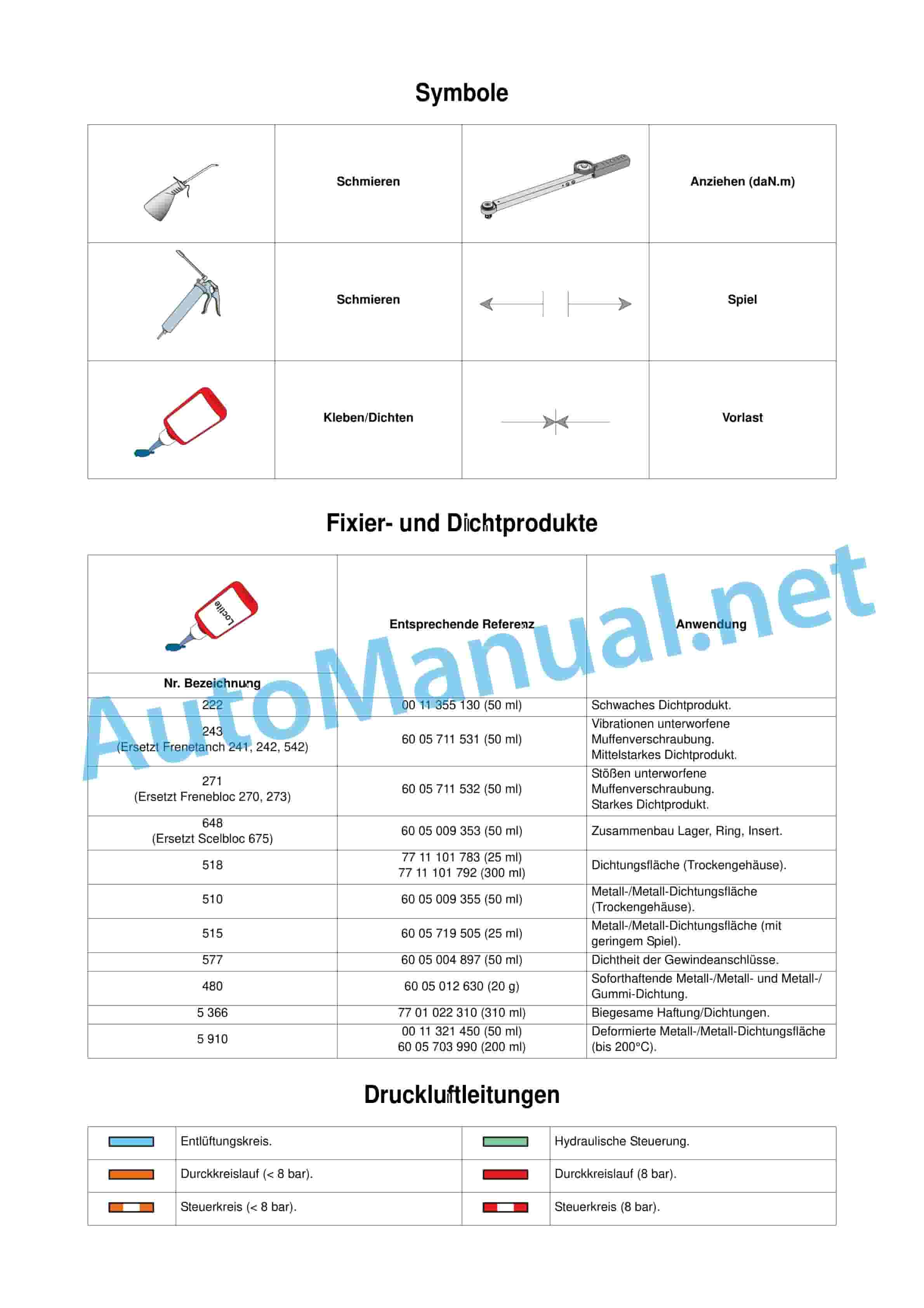
2 fixing and sealing products
3 compressed air lines
4 hydraulic lines
5 standardized tight
2.2 Error codes
2.3 List of error codes
Size(0.6 MB) 5.12.2009.pdf
Table of Content:
1.1 00 0178 310 0
1.2 00 0178 320 0
1.3 00 1133 549 0
1.4 00 1134 145 0
1.5 00 1134 146 0
1.6 00 1135 095 0
1.7 00 1135 452 0
1.8 00 1136 081 0
1.9 00 1137 811 0
1.10 60 0500 531 0
1.11 60 0500 550 4
1.12 60 0500 550 7
1.13 60 0500 550 9
1.14 60 0500 551 0
1.15 60 0500 632 0
1.16 60 0500 653 4
1.17 60 0500 653 5
1.18 60 0500 653 6
1.19 60 0500 653 7
1.20 60 0500 653 8
1.21 60 0500 653 9
1.22 60 0500 654 9
1.23 60 0500 655 0
1.24 60 0500 655 1
1.25 60 0500 551 7
1.26 60 0500 552 0
1.27 60 0500 552 8
1.28 60 0500 553 1
1.29 60 0500 553 2
1.30 60 0500 557 3
1.31 60 0500 557 6
1.32 60 0500 557 7
1.33 60 0500 559 4
1.34 60 0500 559 5
1.35 60 0500 571 8
1.36 60 0500 572 6
1.37 60 0500 573 4
1.38 60 0500 615 3
1.39 60 0500 615 5
1.41 60 0500 670 4
1.42 60 0500 675 8
1.43 60 0500 691 8
1.44 60 0503 324 9
1.45 60 0503 325 0
1.46 60 0571 280 0
1.47 60 0571 297 1
1.48 77 0002 966 5
1.49 77 0002 966 6
1.50 77 0002 966 7
1.51 77 0005 436 1
1.52 77 0006 523 6
1.53 77 0138 800 8
1.54 77 0138 803 1
1.55 77 0138 804 7
1.56 77 0138 808 4
1.57 77 0138 811 0
1.58 77 0138 811 1
1.59 77 0138 812 7
1.60 77 0138 818 0
1.61 77 0138 890 7
1.62 77 1113 251 7
Size(0.9 MB) 5.12.2009.pdf
Table of Content:
1.1 J1 – Attachment points
2 J1_001-002_ARION_630-610_C_REPARATION_02A.pdf
2.1 Attachment points
Size(11.2 MB) 5.12.2009.pdf
Table of Content:
1.1 C1 – General
1.2 C2 – Drive bevel gear
1.3 C3 – Differential
1.4 C4 – PTO shaft
1.5 C5 – Handbrake
1.6 C6 – Service brake
1.7 C7 – Rear axle funnel
2 C1_001-002_ARION_630-610_C_REPARATION_DE.pdf
2630-610_C_REPARATION_A3_DE.pdf
3.1 Longitudinal section view of the rear axle
3.2 Cross-sectional view of the rear axle
4 C1_005-008_ARION_630-610_C_REPARATION_DE.pdf
4.1 Rear axle funnel “HD”
4.2 Rear axle funnel “SHD”
4.3 Tool for self-production
5 C2_001-006_ARION_630-610C_REPARATION_DE.pdf
5.1 C2 drive bevel gear
6 C3_001-014_ARION_630-610C_REPARATION_DE.pdf
6.1 C3 Differential
7 C4_001-034_ARION_630-610C_REPARATION_DE.pdf
7.1 Rear PTO clutch
7.2 Upper rear power take-off shaft
7.3 Lower rear power take-off shaft
7.4 Encoder and PTO shaft operation
7.5 Proportional PTO
8 C5_001-010_ARION_630-610C_REPARATION_DE.pdf
8.1 Exploded View
8.2 Expansion
8.3 Replacement
8.4 Setting mechanism
8.5 Setting the shift fork
9 C6_001-012_ARION_630-610C_REPARATION_DE.pdf
9.1 Operational transfer
9.2 Brake line gearbox
10 C7_001-022_ARION_630-610C_REPARATION_DE.pdf
10.1 Rear axle funnel “HD”
10.2 Rear axle funnel “SHD”
Size(11.8 MB) 5.12.2009.pdf
Table of Content:
1 A1_001-004_ARION_630-610C_DIAGNOSTIC_DE.pdf
1.1 A1 Motor
2 A1_005-006_ARION_630-610_C_DIAGNOSTIC_A3_02A.pdf
2.1 Tightening torques and sealing products
3 A0_001-006_ARION_630-610_C_DIAGNOSTIC_TDM_DE.pdf
3.1 Content
4 A1_007-058_ARION_630-610_C_DIAGNOSTIC_DE.pdf
4.1 Injection data sheets
4.2 Data sheets
4.3 Electronic injection
4.4 Measurements and controls
4.5 Data sheets
4.6 Starting
4.7 Pre-glow system
4.8 Environmental protection
4.9 Environmentally friendly control
4.10 Lubrication
4.11 Measurement and control
4.12 Data sheets
4.13 Cooling
4.14 Measurement and control
4.15 Control and automation
4.16 Protective devices and automation
Size(12.5 MB) 9.12.2012.pdf
Table of Content:
1 Content”Quadrishift”
1.3 B3 – “REVERSHIFT”
1.4 B4 – Robotized switching groups
1.5 B5 – “Creep speed” switching group
1.6 B6 – “Extra creep speed” switching group
2 B1_001-002_ARION_630-610C_REPARATION_DE.pdf
2.1 B1 General
3 B1_003-008_ARION_630-610C_REPARATION_A3_DE.pdf
3.1 Most important settings
3.2 Tightening torques and sealing products
3.3 pairs and sealed specific workflow control.
3.4 Expansion
4 B3_001-016_ARION_630-610C_REPARATION_DE.pdf
4.1 B3 REVERSHIFT
5 B4_001-020_ARION_630-610C_REPARATION_DE.pdf
5.1 Tool for self-production
5.2 Exploded view
5.3 Removing the switching group module
5.4 Removing the switching group module
5.5 Removing the primary line
5.6 Reinstalling the primary line
5.7 Removing the secondary line
5.8 Reinstalling the secondary line
5.9 Adjusting the shafts in the housing
5.10 Measuring the shaft clearances in the housing
5.11 Reinstalling the switching group module
6 B5_001-006_ARION_630-610C_REPARATION_DE.pdf
6.1 Exploded view
6.2 Removing/reinstalling the unit
6.3 Removal/adjustme4 Setting the shift fork
7 B6_001-006_ARION_630-610C_REPARATION_DE.pdf
7.1 Exploded view
7.2 Removing/reinstalling the unit
7.3 Removal/adjustment and reinstallation of the switching device
7.4 Setting the shift fork
8 B2_001-016_ARION_630-610C_REPARATION_DE.pdf
8.1 B2 Quadrishift
Size(15.6 MB) 10.22.2012.pdf
Table of Content:
1 HELP USING TECHNICAL SUPPORT
1.1 F0 General
1.2 This section applies to all parts numbered in Chapter F. Each board is initially shown in a 2D view with the list of relays and fuses. They are then shown schematically in one or more views.
1.3 F1 functional circuit diagrams
1.4 Each wiring diagram shows the set of organs, boards and their connections responsible for a specific use function, such as the control of the front linkage or the fuel level gauges (see below).
1.5 F2 connection diagrams
1.6 This section lists all connectors, intermediate connectionchannels and the associated cables (see below).
1.7 F3 Installation plans
1.8 This section allows precise knowledge of the location of the individual electrical parts in the vehicle.
1.9 Content
2 ListCLAAS COMPONENT NUMBER (CCN)
3 List of connections
4 General wiring
5 List of cable sets
6 list of ground points
7 fuse and electronic boards
7.1 Primary consumer board
7.2 Allocation of conductors
7.3 Allocation of conductors
7.4 Primary consumer board
7.5 Cabin fuse board above V21.3
7.6 Allocation of conductors
7.7 Cabin fuse board above V21.3
8 F1_001_066_ARION_630-610C_DIAGNOSTIC_DE.pdf
8.1 Content
9 F2_001_128_ARION_630_610C_DIAGNOSTIC_DE.pdf
9.1 F2 connection diagrams
10 F3_001_032_ARION_630-610C_DIAGNOSTIC_DE.pdf
10.1 Content
10.2 Notes
Size(16.2 MB) 10.14.2013.pdf
Table of Content:
1 B0_001-004_ARION_630-610_C_DIAGNOSTIC_TDM_DE.pdf
1.1 Content
2 B1_001-006_ARION_630-610_C_DIAGNOSTIC_DE.pdf
3 B1_007-010_ARION_630-610_C_DIAGNOSTIC_A3_DE.pdf
3.1 Most important settings
3.2 Tightening torques and sealing products
4 B2_001-028_ARION_630-610_C_DIAGNOSTIC_DE.pdf
4.1 B2 REVERSHIFT
5 B3_001-016_ARION_630-610_C_DIAGNOSTIC_DE.pdf
5.1 B3 QUADRISHIFT
6 B4_001-030_ARION_630-610_C_DIAGNOSTIC_DE.pdf
6.1 B4 Robotized switching groups
7 B5_001-020_ARION_630-610_C_DIAGNOSTIC_DE.pdf
7.1 B5 reduction gear
8 B6_001-016_ARION_630-610_C_DIAGNOSTIC_DE.pdf
8.1 B6 Automatic
Size(26.9 MB) 10.22.2012.pdf
Table of Content:
1.1 Electronics
2 A1_001-014_ARION_630-610_C_CCN_ELECTRONIQUE_DE.pdf
2.1 Overview
2.2 Technical description
2.3 Communication networks
2.4 Distribution of functions
2.5 Arrangement of components
2.6 Storage of error codes
2.7 Engine speed specification
2.8 Engine speed display
2.9 Trl speed
2.13 CLAAS component number
3 A2_001-186_ARION_630-610_C_CCN_ELECTRONIQUE_DE.pdf
3.1 Motor module “ENG A15”
3.2 Gearbox module “TR1 A57-1″
3.3 Gearbox module TR2 A57-2
3.4 Transmissio”A58”
3.6 Dashboard and CAN network communication module “DBD A101″
3.7 Fuel pressure sender B42
3.8 Fuel temperature sensor B44?”B123”
3.11 Rear hitch position sensor B139
“B144-1” and right “B144-2″ force sensor
3.14 Cool intake air temperature sensor B222
3.15 Sensor for water in fuel B225
3.16 Theoretical speed sensor B227
3.17 Engine speed sensor (on clutch bell PTO shaft) B228
3.18 Intermediate speed sensor gearbox B229
3.19 Crankshaft position and engine speed sensor B231
3.20 Distributor position and engine speed sensor B232
3.21 Recycling actuator M41
3.22 Cold start resistor R15
3.23 Fuel level R35
3.24 Angle position senstch of the rear power lift U57, U58
3.37 Hitch control panel V22
3.38 Solenoid valve 4 wheel drive Y1″Y325”
3.43 “Revershift” solenoid valves, “Y327” and “Y328”
3.44 Solenoid valve for powershift stages “Y335”
3.45 Rear power lift raising/lowering solenoid valve “Y336”, “Y337”
3.46 PTO brake solenoid valve Y338
3.47 Solenoid valve for robotized group Y339
3.48 pneumatic solenoid valve. Brake Y340
3.49 Solenoid valve for dosing (high pressure pump) Y344
3.50 Presence detection contactor Z5
3.51 Handbrake contactor Z12
3.52 Air conditioning gas pressure switch Z21
3.53 Air conditioning thermostat Z24
3.54 Engine oil pressure switch Z42
3.55 Air filter clogging contactor Z69
3.56 Brake fluid level switch 610_C_CCN_METHOD_TDM_DE.pdf
4.1 Content
5 B1_001-048_ARION_630-610_C_CCN_METHOD_DE.pdf
5.1 Accumulator
5.2 Electronics housing
5.3 Electronic gearbox “Auto 5”
5.4 Water sensor
5.5 Hall sensor
5.6 Inductive encoder with variable magnetic resistance
5.7 Encoder with flexible plate
5.8 Magneto-elastic encoder
5.9 Pressure sensor (rheostat)
5.10 Temperature sensor (hot conductor)
5.11 Magnetic switch of the supply circuit
5.12 Detection contactor
5.13 Earth contact
5.14 Proportional solenoid valve
5.15 On/Off controlled solenoid valve
5.16 Control element
5.17 Electric motor
5.18 Photoresistor
5.19 Potentiometer
5.20 Radar
5.21 Relay
5.22 Resistance
5.23 Solenoid
Size(3.3 MB) 5.12.2009.pdf
Table of Content:
1 D3_001-012_ARION_630-610_C_DIAGNOSTIC_DE.pdf
1.1 Overview
1.2 Technical data
1.3 Functional diagram
1.4 Measurements and controls
1.5 MECHANICAL PART
1.6 Hydraulic part for control
1.7 Electronic part
1.8 Lubrication hydraulic unit
1.9 Data sheets
2 D0_000-004_ARION_630-610_C_DIAGNOSTIC_TDM_DE.pdf
2.1 Content
3 630-610_C_DIAGNOSTIC_DE.pdf
3.1 Overview
3.2 Property
3.3 Transmission of movement
3.4 MECHANICAL PART
4 D2_001-012_ARION_630-610_C_DIAGNOSTIC_DE.pdf
4.1 Overview
4.2 Functional diagram
4.3 Schematic representation
4.4 Measurements and controls
4.5 MECHANICAL PART
4.6 Hydraulic part for control
4.7 Electronic part
4.8 Data sheets
Size(3.4 MB) 6.13.2009.pdf
Table of Content:
1.1 D1 – Rigid front axle 20.22
2 D1_003-004_ARION_630-610C_REPARATION_A3_DE.pdf
2.1 Tightening torques and sealing products
3 D1_005-022_ARION_630-610C_REPARATION_DE.pdf
3.1 Preparatory steps for an intervention on the front axle
3.2 Planetary gear reducers and wheel hubs
3.3 Wheel bolt
3.4 Drive bevel gear and differential
4 D2_001-012_ARION_630-610C_REPARATION_DE.pdf
4.1 Exploded view of the gearbox
4.2 Cross-sectional view of the gearbox (assembly with proportional PTO)
4.3 Cross-sectional view of the gearbout proportional PTO)
4.4 Tool for self-production
4.5 Removing the power take-off clutch
4.6 Removing the clutch
4.7 Reinstalling the clutch
4.8 Reinstalling the clutch
4.9 Final work
Size(31.2 MB) 5.12.2009.pdf
Table of Content:
1.1 A1 – GENERAL
1.2 A2 – Cylinder head and valves
1.3 A3 – cylinder liners, pistons, connecting rods
1.4 A4 – flywheel, bearings and crankshaft
1.5 A5 – Valve control and balance shaft
1.6 A6 – Injection
1.7 A7 – Lubrication circuit
2 A1_001-002_ARION_630-610C_REPARATION_DE.pdf
2.1 A1 General
3 A1_003_004_ARION_630-610C_REPARATION_A3_DE.pdf
3.1 Tightening torques and sealing products
4 A1_005-006_ARION_630-610C_REPARATION_DE.pdf
4.1 Wedging between oil pan / front axle frame
5 A2_001-028_ARION_630-610_C_REPARATION_DE.pdf
5.1 A2 cylinder head and valves
6 A3_001-022_ARION_630-610C_REPARATION_DE.pdf
6.1 A3 cylinder liners, pistons, connecting rods
7 A5_001-016_ARION_ON_DE.pdf
7.1 Bore dimension of the camshaft ring
7.2 Measuring the axial play of the camshaft
7.3 Measuring the diameters of the camshaft ring and pins
7.4 Measuring the cam height
7.5 Measuring the axial play of the freewheel gear
7.6 Measuring the backlash of the camshaft drive gears
7.7 Removing the water pump
7.8 Dismantling the water pump
7.9 Mounting the water pump
7.10 Reinstalling the water pump
7.11 Dismantling the front cover
7.12 Removing the pressure regulator
7.13 Reinstalling the pressure regulator
7.14 Removing the camshaft and wear ring
7.15 Reinstalling the camshaft and wear ring
7.16 Removing the front plate
7.17 Reinstalling the front panel
7.18 Motor control setting
7.19 Reinstalling the valve control housing
8 A6_001-012_ARION_630-610C_REPARATION_DE.pdf
8.1 Removing the supply pump
8.2 Reinstalling the supply pump
8.3 Expansion of the high-pressure common rail
8.4 Reinstalling the high-pressure common rail
8.5 Removing the flow controller
8.6 Reinstalling the flow regulators
8.7 Removing the pressure limiter
8.8 Reinstalling the pressure limiter
8.9 Removing the high pressure pump
8.10 Reinstalling the high pressure pump
8.11 Removing the high pressure pump filter
8.12 Reinstalling the high pressure pump filter
8.13 Removing the solenoid valve
8.14 Reinstalling the solenoid valve
8.15 Removing the electronic injectors
8.16 Reinstalling the electronic injectors
9 A7_001-008_ARION_630-610C_REPARATION_DE.pdf
9.1 Removing the oil filter and bracket
9.2 Installing the oil filter and bracket
9.3 Removing the oil cooler
9.4 Installation of the oil cooler
9.5 Attaching the engine oil pan
9.6 Removing the oil pump
9.7 Reinstalling the oil pump
9.8 Installing the engine oil pan
10 A4_001-016_ARION_630-610C_REPARATION_DE.pdf
10.1 Measuring the inner diameter of the crankshaft journals and bearings
10.2 Measuring the width of the stop pins and bearings
10.3 Checking the axial play of the crankshaft
10.4 Removing the damper disc
10.5 Reinstalling the damper disc
10.6 Removing the front bearing bush seal
10.7 Reinstalling the front bearing bush seal
10.8 Removing the engine flywheel
10.9 Reinstalling the engine flywheel
10.10 Removing the rear bearing bush seal
10.11 Reinstalling the rear bearing bush seal
10.12 Removing the flywheel housing
10.13 Removing the flywheel housing
10.14 Removing the locking wheel
10.15 Reinstalling the locking wheel
10.16 Removing the crankshaft gear
10.17 Reinstalling the crankshaft gear
10.18 Removing the crankshaft bearings and the crankshaft
10.19 Reinstalling the crankshaft bearings and the crankshaft
Size(4.4 MB) 5.12.2009.pdf
Table of Content:
1.1 H1 – Raising the cabin
1.2 H2 – Air conditioning/heating
2 H1_001-016_ARION_630-610C_REPARATION_DE.pdf
2.1 H1 Raising the cabinION_630-610C_REPARATION_DE.pdf
3.1 H2 air conditioning/heating
Size(5.6 MB) 5.12.2009.pdf
Table of Content:
1.1 E1 – General
1.2 E2 – Hydraulic supply
1.3 E3 – rear power lift
1.4 E4 – control valve
1.5 E5 – Steering
2 E1_001_002_ARION_630-610C_REPARATION_DE.pdf
2.1 E1 GENERAL
3 E1_003_004_ARION_630-610C_REPARATION_A3_DE.pdf
3.1 Specific torques and sealants
4 E4_001_006_ARION_630-610C_REPARATION_DE.pdf
4.1 E4 control valve
5 E2_001_008_ARION_630-610C_REPARATION_DE.pdf
5.1 E2 hydraulic supply
6 E3_001_006_ARION_630-610_C_REPARATION_DE.pdf
6.1 E3 rear power lift
7 E5_001_012_ARION_630-610C_REPARATION_DE.pdf
7.1 E5 Steering
Size(8 MB) 5.12.2009.pdf
Table of Content:
1 C1_001-012_ARION_630-610_C_DIAGNOSTIC_DE.pdf
1.1 C1 rear axle
2 C2_001-032_ARION_630-610_C_DIAGNOSTIC_DE.pdf
2.1 C2 rear PTO
3 C3_001-004_ARION_630-610_C_DIAGNOSTIC_DE.pdf
3.1 C3 handbrake
4 C6_001-038_ARIO4.1 General description
4.2 Generation of compressed air energy
4.3 Pneumatic brake
4.4 Data sheets
5 C0_001-008_ARION_630-610_C_DIAGNOSTIC_TDM_DE.pdf
5.1 Content
6 C4_001-008_ARION_630-610_C_DIAGNOSTIC_DE.pdf
6.1 General description
6.2 Measurements and controls
6.3 Hydraulic part
6.4 Data sheets
7 C5_001-004_ARION_630-610_C_DIAGNOSTIC_DE.pdf
7.1 General description
Size(9.3 MB) 4.24.2013.pdf
Table of Content:
1 E1_001_002_ARION_630-610C_DIAGNOSTIC_DE.pdf
1.1 E1 Hydraulic
2 E1_003_006_ARION_630-610_C_DIAGNOSTIC_A3_DE.pdf
2.1 Hydraulic diagram
2.2 Lubrication arrangement for 60 l/min and 98 l/min
3 E3_001_014_ARION_630-610C_DIAGNOSTIC_DE.pdf
3.1 E3 control valves
4 E4_001_010_ARION_630-610C_DIAGNOSTIC_DE.pdf
4.1 E4 Steering
5 E0_001_006_ARION_630-610_C_DIAGNOSTIC_TDM_DE.pdf
5.1 Content
6 E1_007_046_ARION_630-610_C_DIAGNOSTIC_DE.pdf
6.1 CLAAS Component Number
6.2 Hydraulics 60 l/Min
6.3 Hydraulics 98014_ARION_630-610_C_DIAGNOSTIC_DE.pdf
7.1 E2 rear power lift
John Deere Repair Technical Manual PDF
John Deere Repair Technical Manual PDF
John Deere Repair Technical Manual PDF
John Deere 16, 18, 20 and 24HP Onan Engines Component Technical Manual CTM2 (19APR90)
John Deere Parts Catalog PDF
John Deere Harvesters 8500 and 8700 Parts Catalog CPCQ24910 Spanish
John Deere Repair Technical Manual PDF
John Deere Repair Technical Manual PDF
John Deere Diesel Engines POWERTECH 2.9 L Component Technical Manual CTM126 Spanish
John Deere Parts Catalog PDF
John Deere Tractors 7500 Parts Catalog CPCQ26568 30 Jan 02 Portuguese
John Deere Repair Technical Manual PDF
John Deere Application List Component Technical Manual CTM106819 24AUG20
John Deere Repair Technical Manual PDF

