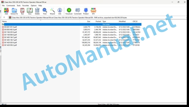
Claas Atos 350-330 (A79) Tractors Operator Manual EN
$50.00
- Model: Atos 350-330 (A79) Tractors
- Type Of Manual: Operator Manual
- Language: EN
- Format: PDF(s)
- Size: 337 MB
File List:
00 0301 051 0.pdf
00 0303 482 0.pdf
00 1166 305 0.pdf
00 1169 984 0.pdf
00 1405 164 7.pdf
00 1405 184 7.pdf
00 1420 028 4.pdf
00 1420 056 2.pdf
00 0301 051 0.pdf:
PROFI CAM 3
Table of contents
1 Introduction
1.1 Notes on the manual
1.1.1 Validity of manual
1.1.2 Information about this Operator’s Manual
1.1.3 Symbols and notes
1.1.4 Optional equipment
1.1.5 Qualified specialist workshop
1.1.6 Maintenance information
1.1.7 Warranty notes
1.1.8 Spare parts and technical questions
1.2 Intended use
1.2.1 Intended use
1.2.2 Reasonably foreseeable misuse
2 Safety
2.1 Identifying warnings
2.1.1 Hazard signs
2.1.2 Signal word
2.2 Safety rules
2.2.1 Meaning of Operator’s Manual
2.2.2 Observing safety decals and warnings
2.2.3 Optional equipment and spare parts
3 Product description
3.1 Overview and method of operation
3.1.1 How the PROFI CAM works
3.2 Identification plates and identification number
3.2.1 Position of identification plates
3.2.2 Explanation of PROFI CAM identification plate
3.3 Information on the product
3.3.1 CE marking
4 Operating and control elements
4.1 Camera system
4.1.1 Camera system monitor
4.2 Menu structure
4.2.1 Main menu
4.2.2
4.2.3
4.2.4
4.2.5
4.2.6
5 Technical specifications
5.1 PROFI CAM
5.1.1 Monitor
5.1.2 Camera
5.1.3 Switch box
5.1.4 Degree of protection against foreign bodies and water
6 Preparing the product
6.1 Shutting down and securing the machine
6.1.1 Switching off and securing the machine
6.2 Prior to operation
6.2.1 Carry out prior to operation
6.2.2 Installing the sun protection
6.2.3 Aligning the camera
6.2.4 Connecting the camera electrics
7 Operation
7.1 Monitor
7.1.1 Switching on the monitor
7.1.2 Calling up the menu
7.1.3 Setting a menu item
7.1.4 Setting the image orientation
7.1.5 Setting automatic screen darkening
7.1.6 Image mirroring
7.1.7 Setting the trigger view
7.1.8 Setting the follow-up time for trigger view
7.1.9 Setting the display mode
7.1.10 Activating/deactivating a display mode
8 Faults and remedies
8.1 Electrical and electronic system
8.1.1 Overview of problems on PROFI CAM camera system
8.1.2 Replacing the switch box fuse
9 Maintenance
9.1 Maintenance intervals
9.1.1 Every 10 operating hours or daily
9.2 Camera system
9.2.1 Checking the camera system for dirt
9.2.2 Cleaning the camera
9.2.3 Cleaning the switch box
9.2.4 Cleaning the monitor
10 Placing out of operation and disposal
10.1 General Information
10.1.1 Putting out of operation and disposal
11 Technical terms and abbreviations
11.1 Abbreviations
11.1.1 Units
11.1.2 Abbreviations
11.1.3 Technical terms
00 0303 482 0.pdf:
PROFI CAM 4
Table of contents
1 Introduction
1.1 Notes on the manual
1.1.1 Validity of manual
1.1.2 Information about this Operator’s Manual
1.1.3 Symbols and notes
1.1.4 Optional equipment
1.1.5 Qualified specialist workshop
1.1.6 Maintenance information
1.1.7 Notes on warranty
1.1.8 Spare parts and technical questions
1.2 Intended use
1.2.1 Intended use
1.2.2 Reasonably foreseeable misuse
2 Safety
2.1 Identifying warnings
2.1.1 Hazard signs
2.1.2 Signal word
2.2 Safety rules
2.2.1 Meaning of Operator’s Manual
2.2.2 Structural changes
2.2.3 Optional equipment and spare parts
2.2.4 Operation only following proper putting into operation
2.2.5 Technical status
2.2.6 Respecting technical limit values
Respecting technical limit values
2.2.7 Hazards when driving on roads and fields
3 Product description
3.1 Overview and method of operation
3.1.1 How the PROFI CAM works
3.2 Identification plates and identification number
3.2.1 Identification plates
3.3 Information on the product
3.3.1 CE marking
4 Operating and display elements
4.1 Camera system
4.1.1 Camera system monitor
4.1.2 CEBIS
4.2 Menu structure
4.2.1 Main menu
4.2.2
4.2.3
4.2.4
4.2.5
4.2.6
5 Technical specifications
5.1 PROFI CAM
5.1.1 Monitor
5.1.2 Camera
5.1.3 Switch box
6 Preparing the product
6.1 Switching off and securing the machine
6.1.1 Switching off and securing the machine
6.2 Prior to putting into operation
6.2.1 Carry out prior to operation
6.2.2 Installing the sun protection
6.2.3 Aligning the camera
7 Operation
7.1 Monitor
7.1.1 Switching on the monitor
7.1.2 Calling up the menu
7.1.3 Setting a menu item
7.1.4 Setting the image orientation
7.1.5 Setting automatic screen darkening
7.1.6 Image mirroring
7.1.7 Setting the trigger view
7.1.8 Setting the follow-up time for trigger view
7.1.9 Setting the display mode
7.1.10 Activating/deactivating a display mode
8 Faults and remedies
8.1 Electric and electronic system
8.1.1 Overview of problems on PROFI CAM camera system
9 Maintenance
9.1 Maintenance intervals
9.1.1 Every 10 operating hours or daily
9.2 Camera system
9.2.1 Checking the camera system for dirt
9.2.2 Cleaning the camera
9.2.3 Cleaning the switch box
9.2.4 Cleaning the monitor
10 Putting out of operation and disposal
10.1 General information
10.1.1 Putting out of operation and disposal
11 Technical terms and abbreviations
11.1 Abbreviations
11.1.1 Units
11.1.2 Abbreviations
11.1.3 Technical terms
00 1166 305 0.pdf:
ATOS 350-340-330
Table of contents
1 To this Operator’s Manual
1.1 Notes on the manual
1.1.1 Using the operator’s manual
Important information concerning this operator’s manual
Structure based on tractor sub-assemblies
Search and find
Specific terminology
1.1.2 Information about this Operator’s Manual
1.1.3 Symbols and instructions
Text and illustrations
Highlighting dangers and warnings
1.1.4 Optional equipment
1.1.5 Qualified specialist workshop
1.1.6 Icons for location of components
1.1.7 Validity of the operator’s manual
1.1.8 Technical information
2 Safety
2.1 Safety rules
2.1.1 Appropriate use
2.1.2 Inappropriate use
2.1.3 European regulations
2.1.4 Preparing the tractor
2.1.5 Safety and accident prevention instructions
Safety devices
Evaluating risks
2.1.6 User/operator recommendations
Essential requirements when operating the tractor
Required clothing
Ensure complete control of the tractor
Keeping children away
2.1.7 Danger zones on the tractor
2.1.8 Driving the tractor
Good driving practices
Good driving practices on sloping ground
2.1.9 Behaviour in case of voltage flash-over from overhead lines and when lightning strikes
2.1.10 Checking the condition of the tractor
2.1.11 Climbing into the cab and out of the tractor
Climbing into the tractor
Climbing out of the tractor
2.1.12 Passenger seat
2.1.13 Cab
Safety structure of the cab
Polluted environment
2.1.14 Precautions to be taken before starting up
2.1.15 Hitching implements
2.1.16 Adjustments and maintenance work
Special notes on mounting the tractor on axle stands
2.1.17 Using the front and rear power take-off
2.1.18 Fuel
2.1.19 Engine coolant
2.1.20 Air conditioning
2.1.21 Electrical system
2.1.22 Applications with front loaders
Raised loads
2.1.23 Forest applications
2.1.24 Stationary working
2.1.25 Implements operating at great depth
2.1.26 Twin wheels
2.2 Safety decals on the tractor
2.2.1 General advice regarding the safety markings
2.2.2 Warning symbols
2.3 Safety devices
2.3.1 Wheel chock
2.3.2 Emergency exits
2.3.3 Extinguisher mounting bracket
3 Tractor description
3.1 Overview
3.1.1 Front left-hand view
3.1.2 Rear right-hand view
3.2 Identification plates and vehicle identification number
3.2.1 Tractor identification plates
Tractor identification number
Tractor regulation type
Tractor serial number
3.2.2 Engine identification plate
Engine serial number
3.2.3 Cab identification plate
4 Operating and display elements
4.1 Cab and operator’s platform
4.1.1 Driving position
Overview of cab components
Overview of components on right-hand side of cab roof
Overview of components on left-hand side of cab roof
Left-hand console of mechanical parking brake
Left-hand console of the hydraulic parking brake
Right-hand console – Mechanical linkage
Area A controls: symbols and functions
Area B controls: symbols and fctions
Area C controls: symbols and functions
Area D controls: symbols and functions
Right-hand console – Electronic linkage
Area A contr symbols and functions
Area B controls: symbols and functions
Area C controls: symbols and functions
Area D controls: symbols and functions
Indicator lights on the rear linkage: symbols and functions
4.1.2 Dashboard
Tractor with mechanical reverser
Front console switches – Tractor with mechanical reverser
Instrument panel buttons – Tractor with mechanical reverser
Tractor with hydraulic reverser
Front console switches – Tractor with hydraulic reverser
Instrument panel buttons – Tractor with hydraulic reverser
4.1.3 Pillars (bottom of the windscreen)
4.1.4 Cab top controls
Overviews
Heating controls
Air conditioning controls
Switch unit, left-hand side
Switch unit, right-hand side
Interior lighting
Overhead light with rocker swi Interior spotlight
Radio (pre-equipment)
Speakers
4.1.5 Digital display
Instrument panel components – Overview
Instrument panel – Indhts
Engine temperature indicator
Fuel level indicator
Main display
Secondary instrument panel display
4.1.6 Control lever for indicator lights, windscreen wiper and horn
Steering column stalk
Turning on the direction indicators
Turning on the high beam headlights
Turning on the windscreen wiper
Operating the screen washer
Sounding the horn
4.1.7 Hinged panels and windows
Types of roof
Standard, non-opening roof with a falling object protective structure (FOPS)
Glazed sunroof with a falling object protective structure (FOPS)
Glazed sunroof with a protective structure other than FOPS
Sunroof blind
Opening and closing the sunroof
Windscreen
Roller sunblind
Side doors
Unlocking and lockine door from outside the cab
Opening the door from inside the cab
4.1.8 Air vents
Overview
4.2 Hydraulic system
4.2.1 Hydraulic valve
4.3 Electric and electronic system
4.3.1 External rear power take-off controls
4.3.2 External controls
Mechanical rear linkage
Electronic rear linkage
4.3.3 Electrical sockets
Rear external sockets
Assignment of the 7-pin socket to the implement road indicators
Internal sockets
5 Technical specifications
5.1 ATOS 350 – 330
5.1.1 Dimensions
5.1.2 Weight
5.1.3 Engine
5.1.4 Gearbox
5.1.5 60 + 60 TRISHIFT transmission, 40 km/h ECO
ATOS 350
5.1.6 40 + 40 TWINSHIFT transmission 40 km/h ECO
ATOS 350
ATOS 340/330
5.1.7 30 + 30 TRISHIFT transmission 40 km/h ECO
ATOS 350
5.1.8 20 + 20 TWINSHIFT transmission 40 km/h ECO
ATOS 350
ATOS 340-330
5.1.9 20 + 20 transmission
ATOS 350
ATOS 340-330
5.1.10 10 + 10 transmission
ATOS 350
ATOS 340-330
5.1.11 Front axle
Four-wheel drive
Two-wheel drive
5.1.12 Tables of front and rear tracks, four-wheel drive tractor
Rims with fixed wheel disc
Rims with variable wheel disc
5.1.13 Tables of front and rear tracks, two-wheel drive tractor
Rims with variable wheel disc
Front tracks
Rims with variable wheel disc
Rear tracks
5.1.14 Tyre combinations
5.1.15 Rear axle
5.1.16 Brakes
5.1.17 Direction
5.1.18 Rear hydraulic linkage
5.1.19 Front linkage
5.1.20 Rear power take-off
5.1.21 Front power take-off
5.1.22 Hydraulic circuit
55 l/min open centre hydraulic circuit
60 l/min ECO open centre hydraulic circuit
5.1.23 Hydraulic control valve combinations
5.1.24 Electricity
5.1.25 Maximum authorised tow weights
5.1.26 Load capacities
5.1.27 Tyre load capacity
Tyre load capacity, four-wheel drive
Tyre load capacity with fixed wheel rim
Tyre load capacity with variable track wheel rim
Tyre load capacity, two-wheel drive
5.1.28 Rear hitches
Rear hitch devices – Archetti
Rear hitch devices – Sauermann
Rear hitch devices – Dromone
5.1.29 Ballast
5.1.30 Cab
5.1.31 Cab specifications
Noise level heard by the driver (according to European Directive 2009/76/EC)
Noise level heard by a passer-by (according to European Directive 2009/63/EC Annex VI)
5.1.32 Driver’s seat vibrations
5.1.33 Lubricants and hydraulic oils
5.1.34 Clutch and brake fluid
5.1.35 Engine coolant
5.1.36 Air conditioning refrigerant
6 Tractor preparation
6.1 Engine
6.1.1 Fuel
Quality requirement
Fuels and additives
Using diesel fuel in winter
6.1.2 Topping up the fuel
6.2 Frame
6.2.1 Adjusting the track on four-wheel drive tractors
Track adjustment – Precautions
Track adjustment – Fixed disc rims
Front wheels assembly diagram
Rear wheels assembly diagram
Track adjustment trriable disc rims
Elements for track adjustment with variable disc rims
Front wheels disc-rim assembly diagram
Rear wheels disc-rim assembly diagram
6.2.2 Adjusting the track on two-wheel drive tractors
Track adjustment – Precautions
Track adjustment
Adjusting the front track width
Rear track width adjustment elements
Rear wheels disc-rim assembly diagram
6.2.3 Definition of the type of steering stop
6.2.4 Adjusting the steering stops for front axle with four end of travel bolts
Fitting the jack
Adjusting the left-hand steering stop
Adjusting the right-hand steering stop
6.2.5 Adjusting the steering stops for front axle with two end of travel bolts
Fitting the jack
Adjusting the left-hand steering stop
Adjusting the right- steering stop
6.2.6 Adjusting the front mudguard
Front fixed mudguard
Fixed front mudguard specifications
Pivoting front mudguards
Pivoting front mudguard specifications
Adjusting the mudguards
6.2.7 General information about the tyres
Checking tyre orientation
6.2.8 Inflation pressure
Effect of tyre inflation when farming and when transporting
Effect on soil compaction
Effect on consumption
6.2.9 Calculation of load distribution
6.2.10 Specifications
Load index
Speed symbol
6.3 Brake
6.3.1 Coupling the brake pedals
6.3.2 Front brake disconnection valve
6.3.3 Trailer hydraulic brake
Description of the hydraulic trailer braking system
Connection of the trailer hydraulic braking system
6.3.4 Trailer compressed air brake
Connection of the trailer compressed air braking system
Checking the pneumatic connection
Periodic inspection of the air braking system
6.4 Steering
6.4.1 Steering column
6.5 Rear power lift
6.5.1 Rear three-point linkage
Warnings
Three-point linkage
6.5.2 Axle stands
6.5.3 Top link
6.5.4 Lateral stabilisers
Stabiliser with lock pin
Adjusting the sideways movement of the lateral stabilisers
Adjusting the length of the lateral stabilisers
Stabiliser with locking clip
Adjusting the sideways movement of the lateral stabilisers
Adjusting the length of the lateral stabilisers
6.5.5 Automatic hitches
Preparing the three-point linkage
Diameter of the implement or equipment hitch pins
Locking the safety catches on the hooks
6.5.6 External controls
Mechanical rear linkage
Electronic rear linkage
6.5.7 Hitching or unhitching an implement
Hitching recommendations
Hitching an implement or equipment
Unhitching an implement or equipment
6.6 Front power lift
6.6.1 Locking the front linkage
Safety measures for transporting implements
Removing and locking the third mounting point
Front linkage locking valve
6.6.2 Mechanical top link
Removing and locking the third mounting point
Selecting the mounting position for the third mounting point
6.6.3 Front lower links
6.6.4 Hitching or unhitching an implement
Hitching recommendations
Hitching
Unhitching
6.7 Front loader
6.7.1 Fitting an adapter frame for the front loader
ATOS 350 with mechanical parking brake – Location of drill holes
ATOS 350 with hydraulic parking brake – Location of drill holes
ATOS 340, 330 – Location of drill holes
6.8 Rear power take-off
6.8.1 Hitching implements to the power take-off
Hitching and unhitching of PTO-driven implements
Hitching an implement
Unhitching the implement
6.8.2 Rear power take-off end fitting
Changing the power take-off output shaft
Starting conditions
Procedure for changing the rear power take-off output shaft
6.9 Front power take-off
6.9.1 Hitching implements to the power take-off
Hitching and unhitching of PTO-driven implements
Hitching an implement
Unhitching the implement
6.10 Hitch
6.10.1 Recommendations
6.10.2 Calculation of the maximum tow load
6.10.3 Swinging drawbar
Horizontal adjustment of the hitch bar
Adjusting the length of the hitch bar
Adjusting the height of the hitch bar
Hitching and unhitching a trailer
6.10.4 Adjusting the height of the hitch devices
Hitch support frame
Hitch devices with height adjustment lever
Hitch devices with height adjustment pins
6.10.5 Clevis drawbars
Hitch device with safety lock
Types of hitch device
Hitching and unhitching a trailer
Hitch device with lock pin
Types of hitch device
Hitching and unhitching a trailer
Types of lock pin
Automatic hitch device
Types of hitch device
Hitching and unhitching a trailer
Semi-automatic hitch device
Types of hitch device
Hitching and unhitching a trailer
Standard hitch
Hitch with safety lock
Hitch support frame with fixed bolt or ball coupling
Types of hitch device
Types of hitch support frame with fixed bolt or ball coupling
Hitching and unhitching a trailer
Hitch with lock pin
Hitch with safety lock
6.10.6 Pick-up hitch
Hydraulic pick-up hitch
Components
Hitching and unhitching a trailer
Types of end fitting
Changing the end fitting
Mechanical pick-up hitch
Components
Hitching and unhitching a trailer
Types of end fitting
Changing the end fitting
6.11 Rear hydraulic system
6.11.1 Rear pressure taps
Hydraulic control valve equipment levels
Overview of the hydraulic control valve controls
Overview of equipment levels
Control valve equipment levels
Two-way control valve
Four-way control valve
Four-way control valve with motorized flow controller
Six-way control valve with motorized flow controller
Six-way control valve
Six-way control valve
Two-way control valve with electronic control
6.11.2 Operation of the hydraulic control valves
6.11.3 Hydraulic connections
Connecting an implement
6.11.4 Oil drip tray
6.11.5 Setting the flow rates
Setting the maximum flow rate for the control valves
6.12 Electric and electronic system
6.12.1 Electrical sockets
Connecting an implement
Electrical connection in the cab
6.12.2 Adjusting the headlights for road travel
Adjusting the headlights
Adjust the headlights
Adjusting the offset lighting
6.12.3 Installing the control unit
Electromagnetic emissions
Correct installation of supplementary equipment
6.13 Cab and operator’s platform
6.13.1 Adjusting the rear-view mirrors
6.13.2 Check the screen washer fluid level
Clean the spray nozzles
Top up the screen washer fluid
6.13.3 Adjusting the GRAMMER MSG85/721 mechanical suspension seat
6.13.4 Adjusting the GRAMMER MSG83/721 mechanical suspension seat
6.13.5 Adjusting the GRAMMER MSG95A/721 air suspension seat
6.13.6 Adjusting the GRAMMER MSG95G/721 air suspension seat
6.13.7 Driver seat belt
Fastening and unfastening the seat belt
6.13.8 Passenger seat
Fastening and unfastening the seat belt
6.13.9 Storage
Document pocket for the operator’s manual
6.13.10 Routing the cables for a control unit
6.14 Assembly parts and machine body
6.14.1 Tool box
6.14.2 Balancing the tractor with mounted implements
Weighing the tractor
Weighing the unladen weight on the front axle in running order
Weighing the unladen weight on the rear axle in running order
Weighing the unladen weight of tractor in running order
Tractor and implement combination
Calculation of loads and distances
Calculation of the load on the front axle
Calculation of the load on the rear axle
Calculation of the total tractor load
Calculation of load distribution
Calculation of the load on the tyres
Calculation example:
6.14.3 Accessing the engine compartment
Opening and closing the bonnet
Removing and fitting the side covers
6.15 Transport of the tractor
6.15.1 Transporting the tractor
6.15.2 Loading the tractor
7 Operation
7.1 Engine
7.1.1 Running in
Recommendations for the first 50 operating hours
Invalidation of the warranty
Recommendations
7.1.2 Starting the engine
7.1.3 Accelerator pedal
7.1.4 Hand accelerator
7.1.5 Engine stops
Switching off the engine
Storing the settings
7.2 Transmission, clutch and driveshaft
7.2.1 Selecting the tractor’s travel direction
Mechanical reverser lever
Engaging and disengaging the direction of travel
Hydraulic reverser lever
Engaging and disengaging the direction of travel
Setting the reverser progressivity
7.2.2 Clutch
7.2.3 SMART STOP – Tractors with hydulic reverser
7.2.4 Selecting gears and ranges
Gear lever
Range lever
Range shift lever
7.2.5 Selecting the work range, gear and direction of travel
Selecting the work range
Selecting the gear
Selecting the direction of travel
Selecting the powershift work ranges
7.2.6 Driving the tractor
7.2.7 Differential lock
Four-wheel drive and differential lock engagement controls
Engaging and disengaging the differential locks manually
7.3 Chassis
7.3.1 Front axle engagement
Front drive axle (four-wheel drive mode) and differential lock controls
Engaging or disengaging the front drive axle manually
7.4 Steering
7.4.1 Dynamic steering
Activating the dynamic steering system
Deactivating the dynamic steering system
7.5 Brake
7.5.1ervice brakes
7.5.2 Parking brake
7.5.3 Hydraulic emergency and parking brake
Using the parking brake
Using the emergency brake
Emergency parking brake release
7.6 Mechanical rear linkage
7.6.1 Mechanical rear linkage controls
Rear linkage elements
Three-point linkage components on the rear linkage
Cab controls
Operating the rear linkage
External controls
7.6.2 Work control mode
7.6.3 Position control
Working using position control
7.6.4 Draft control
Working with the draft control
7.6.5 Mixed draft and position control
7.6.6 Floating position
7.6.7 Controls (examples)
Driving the tractor with the implement raised
Working with a plough (draft control)
Using a seed drill (floating position)
7.7 Electronic rear linkage
7.7.1 Electronic rear linkage controls
Rear linkage elements
Three-point linkage components on the rear linkage
Transport damping system
Cab controls
Control buttons on the console
Setting control knobs and indicator lights
Control knob on the console
External controls
7.7.2 Rear linkage status indicator light
7.7.3 Emergency controls
Emergency manual controls for the rear linkage
7.7.4 Selecting modes
Setting the control mode
7.7.5 Position control
Working depth setting
7.7.6 Upper stop
Setting the maximum lift height
7.7.7 Lowering speed
Lowering speed adjustment
7.7.8 Transport damping system
Activating the transport damping system
7.7.9 Operating the linkage
Unlocking or locking the rear linkage
Rear linkage control
7.8 Front power lift
7.8.1 Front linkage – Recommendations
Good practice when transporting implements
Movement with a tractor equipped with a front linkage
7.8.2 Front linkage controls
Front linkage components
Switching valve
Front linkage control
Positions of front linkage contro
Controlling the front linkage from the cab
Before operating the front linkage
Front linkage control
7.9 Rear power take-off
7.9.1 Rear power take-off contls
Rear power take-off – description and versions
Equipment levels of the rear power take-off
Rear power take-off controls and indicator lights in the cab
Rear power take-off with mechanical linkage and no front power take-off
Rear power take-off with mechanical linkage and with front power take-off
Rear power take-off with electronic linkage
External rear power take-off controls
7.9.2 Selecting the rear power take-off rotation mode and speed
Rear power take-off control lever
Selecting the rear power take-off speed
Rotation mode selection lever
Selecting the rear power take-off rotation mode
7.9.3 Using the power take-off
Controlling the rear power take-off from the cab
Before engaging the rear power take-off
Rear power take-off engagement
Disengaging the rear power take-off
Controlling the rear power take-off from the cab
With mechanical linkage and front power take-off or electronic linkage
Mechanical linkage (without front power take-off)
Controlling the rear power take-off from the ground (with electronic linkage)
Before engaging the power take-off from the ground
Engaging and disengaging the rear power take-off
Automatic mode (electronic linkage)
Operation of the rear power take-off in automatic mode
Engaging and disengaging the rear power take-off automatic control
Examples of power take-off operation in automatic mode
Drive-proportional rear power take-off
Before using the proportional rear power take-off
Engagement of the proportional rear power take-off
7.9.4 Stationary working
7.10 Front power take-off
7.10.1 Using the front power take-off
Front power take-off – description and versions
Introduction to the front power take-off
Front power take-off controls and indicator lights
With mechanical linkage
With electronic linkage
Controlling the front power take-off from the cab
Before engaging the front power take-off
With mechanical linkage
With electronic linkage
7.11 Rear hydraulic system
7.11.1 Operation of the control valves
7.11.2 Rear pressure connectors and controls
Hydraulic control valves with mechanical linkage
Hydraulic control valves with electronic linkage
7.11.3 Mechanically-controlled auxiliary hydraulic control valves
Locking and unlocking the controls
To operate control valves 1, 2, and 3
To operate control valve 4
7.11.4 60 litre economy function (ECO)
7.12 Electric and electronic system
7.12.1 Manual circuit breaker
7.13 Cab and operator’s platform
7.13.1 Manual air conditioning
Cab air conditioning
Technical characteristics of the air conditioning system
7.13.2 Controls in the upper section of the cab
Overhead light with rocker switch
Interior spotlight
8 Faults and remedies
8.1 Alarms
8.1.1 Displaying alarms
8.1.2 General tractor operating faults
8.1.3 Engine operating faults
8.1.4 Transmission operating faults
8.1.5 Power take-off operating faults
8.1.6 Linkage operating faults
8.1.7 Brake operating faults
8.1.8 Hydraulic system operating faults
8.1.9 Hydraulic control valve operating faults
8.1.10 Cab troubleshooting
8.1.11 Electrical system operating faults
8.1.12 Emergencies
8.1.13 Emergency starting
8.1.14 Linkage emergency operation
Emergency control of the rear linkage
8.2 Engine
8.2.1 Faults caused by a low fuel level
8.2.2 Reduction in engine performance
8.3 Frame
8.3.1 Fitting a jack
8.3.2 Replacing a wheel
8.3.3 Towing the tractor
8.3.4 Front emergency hitch device
Hitching and unhitching
8.4 Electric and electronic system
8.4.1 Fuses and relays
Location of fuses and relays
Accessing the fuses and relays
Relays positioned at the front of the dashboard
Fuse box positioned on the right-hand side of the dashboard
Fuses and relays diagram
Allocation of fuses and relays
8.4.2 Configuring the instrument panel
Instrument panel parameters
Setting the time
8.4.3 Replacing the bulbs in the road travel lights
Position of front road lights and bulb types
Position of rear road lights and bulb types
Replacing the high and low beam headlight and offset lighting bulbs
Replacing the side light and front direction indicator bulbs
Replacing the direction indicator, side light and rear brake light bulbs
Replacing the warning beacon bulb
8.4.4 Replacing the interior courtesy light bulbs
Interior courtesy light bulbs
Replacing the rocker type overhead light bulb
Changing the spotlight bulb
8.4.5 Replacing the bulbs in the work lights
Front work lights position and bulb types
Rear work lights position and bulb type
Replacing the bulbs for the front and rear work lights on the top of the cab
Replacing the bulbs for the front work lights n the bottom of the cab and the bonnet work lights
8.4.6 Battery
8.5 Assembly parts and machine body
8.5.1 Frontal impact on the tractor
9 Maintenance
9.1 Maintenance Information
9.1.1 Personal protective equipment
9.1.2 Immobilise the tractor and ensure it is made safe
9.1.3 Cleaning and tidying risk areas
9.1.4 Risks linked to maintenance
Avoiding contamination of food and fodder
Disposing of hazardous liquids or fluids
9.1.5 Welding advice
9.1.6 Protective devices on the tractor
9.1.7 Engine
Alternator
Engine lubrication
Engine cooling
Engine belts
9.1.8 Wheels and tyres
9.1.9 Braking system
9.1.10 Pneuma
John Deere Repair Technical Manual PDF
John Deere Repair Technical Manual PDF
John Deere Repair Technical Manual PDF
John Deere Repair Technical Manual PDF
John Deere PowerTech M 10.5 L and 12.5 L Diesel Engines COMPONENT TECHNICAL MANUAL CTM100 10MAY11
John Deere Repair Technical Manual PDF
John Deere Parts Catalog PDF
John Deere Tractors 7500 Parts Catalog CPCQ26568 30 Jan 02 Portuguese
John Deere Repair Technical Manual PDF
John Deere Diesel Engines PowerTech 4.5L and 6.8L – Motor Base Technical Manual 07MAY08 Portuguese
John Deere Repair Technical Manual PDF
John Deere Repair Technical Manual PDF

