Claas Avero 160 (560) Combines Operator Manual EN
$50.00
- Model: Avero 160 (560) Combines
- Type Of Manual: Operator Manual
- Language: EN
- Format: PDF(s)
- Size: 33.0 MB
File List:
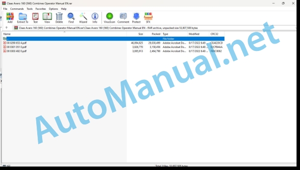
00 0290 653 4.pdf
00 0301 051 0.pdf
00 0303 482 0.pdf
00 0290 653 4.pdf:
AVERO 240 / 160
Table of contents
1 To this Operator’s Manual
1.1 Notes on the manual
1.1.1 Validity of manual
1.1.2 How to use the Manual
1.1.3 Technical data
2.1 Safety rules
2.1.1 General safety warnings
2.1.2 General instructions
2.1.3 Important!
2.1.4 Intended use
2.1.5 Reasonably foreseeable misuse
2.1.6 Safety and accident prevention regulations
2.1.7 Safety and accident prevention regulations for combine-harvesters
2.1.8 Prior to putting into operation, general
2.1.9 Identification of warning and danger signs
2.1.10 Road traffic
2.1.11 General driving operation
2.1.12 Combine harvester driving operation
2.1.13 Driving on slopes
2.1.14 Transporting persons
2.1.15 Leaving the machine
2.1.16 Diesel engine
2.1.17 Hints regarding the diesel engine
2.1.18 Hint regarding the electronic engine management
2.1.19 Anti-freeze
2.1.20 Risk of injury by hydraulic liquid
2.1.21 Air conditioner
2.1.22 Front attachments and trailers
2.1.23 Material discharge / straw discharge
2.1.24 Grain delivery
2.1.25 Additional weights
2.1.26 Accumulator
2.1.27 Adjusting and maintenance work
2.1.28 First aid measures
2.2 Safety decals on the machine
2.2.1 General information on safety decals
2.2.2 Engine
2.2.3 Chassis
2.2.4 Hydraulic system
2.2.5 Cab / operator’s platform
2.2.6 Intake
2.2.7 Threshing mechanism
2.2.8 Separation
2.2.9 Cleaning unit
2.2.10 Crop receptacle / straw receptacle
2.2.11 Grain delivery
2.2.12 Various components / Machine body
2.3 Safety signs
2.3.1 General instructions on safety decals
2.3.2 Chassis
2.3.3 Hydraulic system
2.3.4 Various components / machine body
2.4 Safety devices
2.4.1 Applying the feed rake conveyor safety lock
2.4.2 Folding up the feed rake conveyor safety lock
2.4.3 Securing the machine against rolling away
2.4.4 Battery isolating switch
2.4.5 Fire extinguisher
2.4.6 Emergency exit
3 Machine description
3.1 Overview and method of operation
3.1.1 Overview of front and left side of machine
3.1.2 Overview of rear and right side of machine
3.1.3 Function of machine
3.1.4 Engine overview of CATERPILLAR C-6.6
3.1.5 Overview of cooling units
3.2 Identification plates and vehicle identification number
3.2.1 Spare parts and technical questions
3.2.2 Machine identification plate
Identification plates of machines according to ECE-R 24
Identification plates of machines according to ECE-R 24
Identification plate of machines according to ECE-R 120
3.2.3 Engine identification plate CATERPILLAR C-6.6
3.2.4 Drive axle identification plate
3.2.5 Identification plate of rear axle
3.2.6 Identification plate of trailer hitch
3.2.7 Hitch block identification plate
3.2.8 Cab identification plate
3.2.9 Identification plate of straw chopper
3.2.10 Position of serial no.
4 Operating and control elements
4.1 Cab / Operator’s platform
4.1.1 Overview of operator’s platform
4.1.2 Control panel
4.1.3 B-column operator panel
4.1.4 Cab roof controls
4.1.5 Changing over the drive lights
4.1.6 Fold cutterbar to working position / transport position
4.1.7 Ignition switch
4.1.8 Multifunction handle
4.1.9 Vehicle information unit
4.1.10 Multifunction switch
4.1.11 Adjusting the mechanically suspended driver’s seat (optional equipment)
4.1.12 Adjusting the air-suspended driver’s seat (optional equipment)
4.1.13 Air conditioner
4.1.14 Automatic air conditioner
4.2 Board computer / Indicators
4.2.1 Validity of CIS software
4.2.2 General instructions for CIS
4.2.3 CIS monitor
4.2.4 CIS main menu
Overview of operation main menu
4.2.5 CIS fault types
4.2.6 CIS fault messages
4.2.7 Guideline values for pulses/100 m
5 Technical specifications
5.1 AVERO 240 / 160 – type 451 / 450
5.1.1 General instructions
5.1.2 CATERPILLAR C-6.6 engine
5.1.3 Chassis
5.1.4 Chassis tyre pressure
5.1.5 Chassis wheel tread
5.1.6 Brake
5.1.7 Steering
5.1.8 Electrical / electronic equipment
5.1.9 Cab / operator’s platform
5.1.10 Feeder unit
5.1.11 Threshing mechanism
5.1.12 Separation
5.1.13 Cleaning unit
5.1.14 Grain delivery
5.1.15 Grain delivery dimensions
5.1.16 Dimensions of attachment parts / machine body
5.1.17 Attachment parts / machine body weights
6 Machine preparation
6.1 Shutting down and securing the machine
6.1.1 Stopping and securing the machine
6.2 Access to workplace and maintenance positions
6.2.1 Access to the workplace and maintenance areas
6.3 Prior to operation
6.3.1 Prior to initial operation
6.3.2 Prior to every operation
6.4 Adjusting the machine
6.4.1 Setting the machine to grain harvest
6.4.2 Setting up the machine for harvesting maize
6.4.3 AVERO 240 threshing chart
6.4.4 Threshing chart (AVERO 160)
6.4.5 Sieve chart
6.4.6 Concave segment
6.4.7 Disawner plates
6.4.8 Cleaning the machine prior to a change of seeds
6.5 Loading the machine
6.5.1 Loading and lashing down the machine
6.5.2 Unscrewing the lifting eyes
6.6 Front attachment
6.6.1 Installing the front attachment
6.6.2 Removing the front attachment
6.6.3 Installing universal drive shaft
6.6.4 Removing universal drive shaft
6.6.5 Mounting the multi-coupler
6.6.6 Dismounting the multi-coupler
6.6.7 Suspending the front attachment
6.6.8 Interlocking the front attachment
6.6.9 Unlocking the front attachment
6.6.10 Unhitching front attachment
6.7 Engine
6.7.1 Refuelling the machine
6.8 Chassis
6.8.1 Adjusting the ground speed control lever operating resistance
6.8.2 Removing / installing the wheels
6.8.3 Jacking up the machine
Jacking up the machine beneath the axles
Jack up the machine at the rear beneath the frame
6.8.4 Overview of rear axle
6.8.5 Converting the rear axle from transport to working position
6.8.6 Rear axle 00 0694 220 X – Adjusting the track width
Checking the free movement of the rear axle
Flange width 2239 mm
Flange width 2439 mm
Flange width 2639 mm
6.8.7 Rear axle 00 0694 220 X – Installing the pendulum stop
6.9.1 Adjusting the parking brake
6.9.2 Checking the foot brake
6.10 Hitch
6.10.1 Installing the trailer hitch (additional equipment)
6.10.2 Hitching a trailer
6.10.3 Unhitching the trailer
6.11 Hydraulic system
6.11.1 Checking / filling the front attachment dampening accumulator
6.12 Electrical / Electronic equipment
6.12.1 Installing the air conditioner compressor fuse
6.12.2 Adjusting the drive lights for folding front attachments
6.12.3 Checking the back-up horn
6.13 Cab / Operator’s platform
6.13.1 Installing the side view mirror (additional equipment)
6.13.2 Removing the cab transport safety equipment
6.14 Feeder unit
6.14.1 Checking the anti-slip strips on the feed rake conveyor
6.14.2 Installing / removing the front attachment lock
6.14.3 Adjusting the feeder chain height
6.14.4 Adjusting the front attachment drop rate
6.15 Threshing mechanism
6.15.1 Opening / closing the stone trap
6.15.2 Removing / installing the stone trap cover (AVERO 240) (additional equipment)
6.15.3 Removing / installing the stone trap cover (AVERO 160) (additional equipment)
6.15.4 Opening / closing the drum inspection cover
6.15.5 Removing / installing the preconcave segments (AVERO 240)
6.15.6 Removing / installing threshing concave segments (AVERO 160) (Multicrop concave)
6.15.7 Adjusting the basic concave settings (AVERO 240)
6.15.8 Checking the threshing concave basic setting (AVERO 160)
6.15.9 Installing / removing the threshing drum cover plates (additional equipment)
6.15.10 Installing / removing the rake behind concave / concave plate (additional equipment)
6.16 Separation
6.16.1 Installing / removing the side risers (straw walker machine)
6.16.2 Installing / removing the CCM risers (straw walker machine)
6.16.3 Installing / removing the centre risers (straw walker machines)
6.16.4 Installing / removing rice risers (straw walker machines)
6.17 Cleaning system
6.17.1 Removing the sieves
6.17.2 Installing the sieves
6.17.3 Fitting the sieve web plates (machines without 3-D cleaning system)
6.17.4 Covering / opening the returns line
6.18 Crop discharge / Swath discharge
6.18.1 Adjusting the straw chopper speed
6.18.2 Removing the straw guide plate (straw chopper with deflector spreader)
6.18.3 Installing the straw guide plate (straw chopper with deflector spreader)
6.18.4 Installing / removing the straw chopper rubber blanket (additional equipment)
Installing the rubber blanket
Removing the rubber blanket
6.18.5 Installing / removing the straw chopper stationary knife cover plate (additional equipment)
Installing the cover plate
Removing the cover plate
6.18.6 Straw chopper sieves installation position
6.19 Grain delivery
6.19.1 Entering / leaving the grain tank
6.19.2 Open / close grain tank cover
6.19.3 Adjusting the grain tank fill indicator
6.19.4 Checking / bolting down the drain plug on the grain tank unloading tube
6.20 Various components / Machine body
6.20.1 Fitting an additional weight to the machine
Filling the additional weight into the tyres
Fitting an additional weight to the rear axle
Checking the additional weight due to fitted straw chopper
6.20.2 Selecting the additional weight for the machine
Assignment to rear axle types
Assignment of machine to front attachment
6.20.3 Selecting the additional weight for the tyre
6.20.4 Selecting the additional weight for the rear axle
6.20.5 Opening / closing the side panels
6.20.6 Opening / closing the engine compartment side panel
6.20.7 Opening / closing the rear hood
6.20.8 Opening / closing the grain tank unloading drive stage 2 side panel
7 Operation
7.1 Driving the machine
7.1.1 Preparing road travel
7.1.2 Preparing fieldwork
7.1.3 Driving the machine with the ground speed control lever
Driving forward
Braking the machine
Stopping the machine
Driving backward
7.1.4 Suspend the straw guide rubber
7.2 Engine
7.2.1 Setting the diesel engine speed
7.2.2 Start the diesel engine
7.2.3 Stop the diesel engine
7.3 Chassis
7.3.1 Shifting gears
7.3.2 Driving properties
7.3.3 Towing the machine
7.3.4 Towing forward
7.3.5 Towing in reverse
7.4.1 Engaging the parking brake
7.4.2 Releasing the parking brake
7.4.3 Foot brake
7.4.4 Parking the machine
7.5 Steering
7.5.1 Steering
7.5.2 Adjusting the steering column
7.6 Cab / Operator’s platform
7.6.1 Applying the safety belt*
7.6.2 Adjusting the mechanically suspended driver’s seat (optional equipment)
7.6.3 Adjusting the air-suspended driver’s seat (optional equipment)
7.6.4 Putting the air conditioner into operation
7.6.5 Switching on the automatic air conditioner
7.6.6 Setting the cab temperature automatically
7.6.7 Setting the cab temperature manually
7.6.8 Adjusting the air conditioner air flow rate
7.6.9 De-humidifying the cab window panes
7.6.10 Displaying the outside temperature
7.6.11 Converting the temperature display to �� Fahrenheit
7.6.12 Adjusting the side view mirror (additional equipment)
7.7 Feeder unit
7.7.1 Reversing the front attachment / feed rake conveyor
7.7.2 Engaging the feed rake conveyor (switch console)
7.7.3 Disengaging the feed rake conveyor (switch console)
7.7.4 Disengaging the feed rake conveyor (multifunction handle)
7.8 Ground guidance
7.8.1 Grounance variants
CONTOUR variant
AUTO CONTOUR variant
7.8.2 Cutting height control – Sthe cutting height/ground pressure
7.8.3 Pre-set cutting height control – Saving the cutting height
7.8.4 Position indicator – Reading the ground pressure
7.8.5 Position indicator – Reading the cutting height
7.9 Threshing mechanism
7.9.1 Engage the threshing mechanism
7.9.2 Disengage the threshing mechanism
7.9.3 Adjusting the concave (AVERO 240)
7.9.4 Adjusting the concave (AVERO 160)
7.9.5 Engaging / disengaging the disawner plate (AVERO 240)
7.9.6 Installing / removing disawner bars (AVERO 160) (additional equipment)
7.9.7 Installing / removing the threshing segment (AVERO 240)
7.9.8 Unwrapping the threshing drum (AVERO 240)
7.9.9 Unwrapping the threshing drum (AVERO 160)
7.9.10 Adjusting the threshing drum speed (threshing drum variable-speed drive)
7.9.11 Setting the threshing drum speed (threshing drum chain drive)
7.10 Separation
7.10.1 Adjusting the deflector curtain
7.10.2 Observe straw blockage warning downstream of the separation
7.10.3 Setting the separation performance monitor display
7.11 Cleaning system
7.11.1 Adjusting the sieves manually
7.11.2 Adjusting the fan speed
7.11.3 Adjusting the wind board
7.11.4 Setting the cleaning performance monitor display
7.12 Crop discharge / Swath discharge
7.12.1 Putting the straw chopper into operation (swing deflector spreader to chopping position)
7.12.2 Shut down the straw chopper (swing deflector to swathing position)
7.12.3 Swinging the deflector spreader
Swinging the deflector spreader
7.12.4 Adjusting the stationary knives (standard straw chopper)
7.13 Grain delivery
7.13.1 Adjusting the grain tank auger cover plates (from serial no. …)
7.13.2 Adjusting the grain tank filler auger cover plate (AVERO 160)
7.13.3 Checking the returns
7.13.4 Swinging the grain tank unloading tube out / in
7.13.5 Engaging / disengaging grain tank unloading
7.14 Various components / Machine body
7.14.1 Swing round the front ladder
Front ladder transport position
Up to serial no. …
From serial no. …
Front ladder access position
7.14.2 Adjusting the rear ladder
8 Faults and remedies
8.1 Engine
8.1.1 Diesel engine
8.1.2 Draining the fuel from the fuel tank
8.1.3 Bleeding the fuel system
8.1.4 Diesel engine problems and remedies
8.1.5 Assist-starting (12 V)
Assist-starting (12 V)
Diesel engine jump starting
8.2 Electrical / Electronic equipment
8.2.1 Opening the basic central terminal compartment
8.2.2 Closing the basic central terminal compartment
8.2.3 Opening the roof central terminal compartment
8.2.4 Closing the roof central terminal compartment
8.2.5 Basic central terminal compartment
8.2.6 Roof central terminal compartment
8.2.7 Vehicle main fuse
8.2.8 Back-up fuse of basic / roof central terminal compartment
8.3 Cab / Operator’s platform
8.3.1 Automatic air conditioner fault code table
8.3.2 Air conditioner problems and remedies
8.4 Front attachment
8.4.1 Front attachment
8.5 Feeder unit
8.5.1 Problems with and remedies for the feed rake conveyor
8.6 Threshing mechanism
8.6.1 Problems with and remedies for the threshing mechanism
8.6.2 Threshing drum
8.7 Separation
8.7.1 Problems with and remedies for the separation
8.8 Cleaning system
8.8.1 Problems with and remedies for the cleaning system
8.9 Crop discharge / Swath discharge
8.9.1 Problems with and remedies for discharge / straw discharge
8.10 Grain delivery
8.10.1 Problems with and remedies for grain delivery
8.10.2 Installing the grain tank unloading shear bolt
9 Maintenance
9.1 General Information
9.1.1 General maintenance warnings
9.1.2 Diesel engine
9.1.3 Cleaning the engine compartment and hazard areas
9.1.4 Belts
9.1.5 Variable-speed drives
9.1.6 Proper chain tension
9.1.7 Bolts
9.1.8 Lubrication
9.1.9 Cleanness of lubricants
9.1.10 Brake
9.1.11 Wheels / tyres
9.1.12 Hydraulic system
9.1.13 Electric system
9.1.14 Air conditioner
9.1.15 Protective guards
9.1.16 Spare parts
9.1.17 Unbalance
9.1.18 Welding work on combine harvester
9.1.19 Cleaning of surfaces with decals
9.1.20 Winter storage suggestions for combine harvesters
9.1.21 Coolant
9.2 Operating utilities
9.2.1 Lubricants
9.3 Service intervals
9.3.1 Handling of maintenance intervals
9.3.2 Before the harvest
9.3.3 After the first 10 operating hours
9.3.4 After the first 100 operating hours
9.3.5 After the first 500 operating hours
9.3.6 Every 10 operating hours or daily
9.3.7 Every 50 operating hours
9.3.8 Every 100 operating hours
9.3.9 Every 250 operating hours
9.3.10 Every 500 operating hours or annually
9.3.11 Every 1000 operating hours
9.3.12 Every 2 years
9.3.13 Every 5 years
9.3.14 After the harvest
9.4 Engine
9.4.1 Cleaning the diesel engine surroundings
9.4.2 Closing / opening the fuel system shut-off tap
9.4.3 Cleaning the fuel sediment bowl filter
9.4.4 Draining the condensate on the fuel pre-filter (standard equipment)
9.4.5 Changing the fuel pre-filter (standard equipment)
9.4.6 Draining the condensate at the fuel pre-filter (additional equipment)
9.4.7 Changing the fuel pre-filter (additional equipment)
9.4.8 Changing the additional fuel filter (CATERPILLAR C-6.6) (additional equipment)
9.4.9 Changing the fuel filter on CATERPILLAR C-6.6
9.4.10 Checking the diesel engine oil level
9.4.11 Changing the diesel engine oil / oil filter
9.4.12 Checking the radiator coolant level
9.4.13 Checking the coolant mixing ratio
9.4.14 Changing the radiator coolant
9.4.15 Draining the radiator coolant
9.4.16 Topping up radiator coolant
9.4.17 Preparing the air gun for cleaning the cooling units
9.4.18 Cleaning the rotary chaff screen
9.4.19 Cleaning the cooling unit
9.4.20 Changing the coolant hoses
9.4.21 Cleaning / changing the diesel engine air filter with plastic housing
9.4.22 Changing the diesel engine air filter safety filter element with plastic housing
9.4.23 Cleaning the air intake filter
9.4.24 Changing the air intake hoses
9.4.25 Retightening the air intake hose clamps
9.5 Chassis
9.5.1 Wheels / tyres
9.5.2 Checking the tightening torque of wheel nuts / wheel bolts
9.5.3 Cleaning the surroundings of drive axle manual gearbox
9.5.4 Checking the drive axle final drive oil level
9.5.5 Draining the drive axle final drive oil
9.5.6 Topping up the drive axle final drive oil
9.5.7 Checking the drive axle manual gearbox oil level
9.5.8 Draining the drive axle manual gearbox oil
9.5.9 Topping up the drive axle manual gearbox oil
9.6.1 Checking the brake fluid level
9.6.2 Checking the brake shoes
9.7 Drives
9.7.1 AVERO 240 / 160 drive diagram, left side
9.7.2 AVERO 240 / 160 drive diagram, right side
9.7.3 Adjusting belt (R01)
9.7.4 Adjusting belt (R02)
9.7.5 Adjusting belt (R03)
9.7.6 Adjusting belt (R04)
9.7.7 Adjusting belt (R05)
9.7.8 Adjusting belt (R06)
9.7.9 Adjusting belt (R07)
9.7.10 Adjusting belt (R08)
9.7.11 Adjusting belt (R09)
9.7.12 Adjusting belt (R10)
9.7.13 Adjusting belt (R11)
9.7.14 Adjusting belt (R12)
9.7.15 Adjusting belt (R15)
9.7.16 Adjusting belt (R16)
9.7.17 Removing belt (R40)
9.7.18 Installing belt (R40)
9.7.19 Adjust belt (R40)
9.7.20 Removing the belt (R41)
9.7.21 Installing belt (R41)
9.7.22 Adjusting belt (R41)
9.7.23 Removing belt (R42)
9.7.24 Installing belt (R42)
9.7.25 Adjusting belt (R42)
9.7.26 Removing belt (R43)
9.7.27 Installing belt (R43)
9.7.28 Adjusting belt (R43)
9.7.29 Removing chain (K55)
9.7.30 Installing chain (K55)
9.7.31 Adjusting chain (K55)
9.7.32 Removing chain (K56)
9.7.33 Installing chain (K56)
9.7.34 Adjusting chain (K56)
9.7.35 Removing chain (K57)
9.7.36 Installing chain (K57)
9.7.37 Adjusting chain (K57)
9.7.38 Removing the chain (K58)
9.7.39 Fitting the chain (K58)
9.7.40 Adjusting the chain (K58)
9.8 Hydraulic system
9.8.1 Relieving the pressure accumulator
9.8.2 Checking the hydraulic system oil level
9.8.3 Changing the hydraulic system oil / oil filter / suction filter / fresh air filter element
9.8.4 Cleaning the hydraulic tank filling screen
9.8.5 Venting the cutterbar cross levelling hydraulic cylinder
9.9 Electrical / Electronic equipment
9.9.1 Checking the battery electrolyte level
9.10 Cab / Operator’s platform
9.10.1 Cleaning / replacing the cab air filter
9.10.2 Cleaning the cab recirculation air filter
9.10.3 Cleaning the cab roof units
9.10.4 Checking the air conditioner refrigerant moisture saturation
9.11 Feeder unit
9.11.1 Adjusting the feeder chains
9.11.2 Adjusting the feeder chain slip clutch
9.11.3 Checking the rasp plates on the feed rake conveyor
9.12 Separation
9.12.1 Checking the deflector curtain
9.13 Crop discharge / Swath discharge
9.13.1 Checking the straw chopper
9.13.2 Replacing the straw chopper free-swinging knives
Replacing the worn free-swinging knives
Example: replacing the outside free-swinging knives
Example: replacing the inside free-swinging knives
Replacing the free-swinging knives for grain
Replacing the free-swinging knives for maize
9.14 Grain delivery
9.14.1 Adjusting the returns elevator chain
9.14.2 Adjusting the grain elevator chain
9.14.3 Clean the auger troughs
9.14.4 Clean the grain tank
9.14.5 Adjusting the grain tank unloading tube support transport position
9.15 Various components / Machine body
9.15.1 Checking the fire extinguisher
9.15.2 Check if machine is soiled.
9.15.3 Checking the hydraulic system for leaks
9.15.4 Checking the gearbox for leaks
9.16 Lubrication chart
9.16.1 Lubrication points – 10 h left
9.16.2 Lubrication points – 10 h right
9.16.3 Lubrication points – 50 h left
9.16.4 Lubrication points – 50 h right
9.16.5 Lubrication points – 100 h left
9.16.6 Lubrication points – 100 h right
9.16.7 Lubrication points – 500 h left
9.16.8 Lubrication point – 500 h right
10 Placing out of operation and disposal
10.1 General Information
10.1.1 Removal from service and disposal
11 EC declaration of conformity
11.1 AVERO 240 / 160 – type 451 / 450
11.1.1 EC declaration of conformity
00 0301 051 0.pdf:
PROFI CAM 3
Table of contents
1 Introduction
1.1 Notes on the manual
1.1.1 Validity of manual
1.1.2 Information about this Operator’s Manual
1.1.3 Symbols and notes
1.1.4 Optional equipment
1.1.5 Qualified specialist workshop
1.1.6 Maintenance information
1.1.7 Warranty notes
1.1.8 Spare parts and technical questions
1.2 Intended use
1.2.1 Intended use
1.2.2 Reasonably foreseeable misuse
2.1 Identifying warnings
2.1.1 Hazard signs
2.1.2 Signal word
2.2 Safety rules
2.2.1 Meaning of Operator’s Manual
2.2.2 Observing safety decals and warnings
2.2.3 Optional equipment and spare parts
3 Product description
3.1 Overview and method of operation
3.1.1 How the PROFI CAM works
3.2 Identification plates and identification number
3.2.1 Position of identification plates
3.2.2 Explanation of PROFI CAM identification plate
3.3 Information on the product
3.3.1 CE marking
4 Operating and control elements
4.1 Camera system
4.1.1 Camera system monitor
4.2 Menu structure
4.2.1 Main menu
4.2.2
4.2.3
4.2.4
4.2.5
4.2.6
5 Technical specifications
5.1 PROFI CAM
5.1.1 Monitor
5.1.2 Camera
5.1.3 Switch box
5.1.4 Degree of protection against foreign bodies and water
6 Preparing the product
6.1 Shutting down and securing the machine
6.1.1 Switching off and securing the machine
6.2 Prior to operation
6.2.1 Carry out prior to operation
6.2.2 Installing the sun protection
6.2.3 Aligning the camera
6.2.4 Connecting the camera electrics
7 Operation
7.1 Monitor
7.1.1 Switching on the monitor
7.1.2 Calling up the menu
7.1.3 Setting a menu item
7.1.4 Setting the image orientation
7.1.5 Setting automatic screen darkening
7.1.6 Image mirroring
7.1.7 Setting the trigger view
7.1.8 Setting the follow-up time for trigger view
7.1.9 Setting the display mode
7.1.10 Activating/deactivating a display mode
8 Faults and remedies
8.1 Electrical and electronic system
8.1.1 Overview of problems on PROFI CAM camera system
8.1.2 Replacing the switch box fuse
9 Maintenance
9.1 Maintenance intervals
9.1.1 Every 10 operating hours or daily
9.2 Camera system
9.2.1 Checking the camera system for dirt
9.2.2 Cleaning the camera
9.2.3 Cleaning the switch box
9.2.4 Cleaning the monitor
10 Placing out of operation and disposal
10.1 General Information
10.1.1 Putting out of operation and disposal
11 Technical terms and abbreviations
11.1 Abbreviations
11.1.1 Units
11.1.2 Abbreviations
11.1.3 Technical terms
00 0303 482 0.pdf:
PROFI CAM 4
Table of contents
1 Introduction
1.1 Notes on the manual
1.1.1 Validity of manual
1.1.2 Information about this Operator’s Manual
1.1.3 Symbols and notes
1.1.4 Optional equipment
1.1.5 Qualified specialist workshop
1.1.6 Maintenance information
1.1.7 Notes on warranty
1.1.8 Spare parts and technical questions
1.2 Intended use
1.2.1 Intended use
1.2.2 Reasonably foreseeable misuse
2.1 Identifying warnings
2.1.1 Hazard signs
2.1.2 Signal word
2.2 Safety rules
2.2.1 Meaning of Operator’s Manual
2.2.2 Structural changes
2.2.3 Optional equipment and spare parts
2.2.4 Operation only following proper putting into operation
2.2.5 Technical status
2.2.6 Respecting technical limit values
Respecting technical limit values
2.2.7 Hazards when driving on roads and fields
3 Product description
3.1 Overview and method of operation
3.1.1 How the PROFI CAM works
3.2 Identification plates and identification number
3.2.1 Identification plates
3.3 Information on the product
3.3.1 CE marking
4 Operating and display elements
4.1 Camera system
4.1.1 Camera system monitor
4.1.2 CEBIS
4.2 Menu structure
4.2.1 Main menu
4.2.2
4.2.3
4.2.4
4.2.5
4.2.6
5 Technical specifications
5.1 PROFI CAM
5.1.1 Monitor
5.1.2 Camera
5.1.3 Switch box
6 Preparing the product
6.1 Switching off and securing the machine
6.1.1 Switching off and securing the machine
6.2 Prior to putting into operation
6.2.1 Carry out prior to operation
6.2.2 Installing the sun protection
6.2.3 Aligning the camera
7 Operation
7.1 Monitor
7.1.1 Switching on the monitor
7.1.2 Calling up the menu
7.1.3 Setting a menu item
7.1.4 Setting the image orientation
7.1.5 Setting automatic screen darkening
7.1.6 Image mirroring
7.1.7 Setting the trigger view
7.1.8 Setting the follow-up time for trigger view
7.1.9 Setting the display mode
7.1.10 Activating/deactivating a display mode
8 Faults and remedies
8.1 Electric and electronic system
8.1.1 Overview of problems on PROFI CAM camera system
9 Maintenance
9.1 Maintenance intervals
9.1.1 Every 10 operating hours or daily
9.2 Camera system
9.2.1 Checking the camera system for dirt
9.2.2 Cleaning the camera
9.2.3 Cleaning the switch box
9.2.4 Cleaning the monitor
10 Putting out of operation and disposal
10.1 General information
10.1.1 Putting out of operation and disposal
11 Technical terms and abbreviations
11.1 Abbreviations
11.1.1 Units
11.1.2 Abbreviations
11.1.3 Technical terms
John Deere Repair Technical Manual PDF
John Deere Repair Technical Manual PDF
John Deere Repair Technical Manual PDF
John Deere Repair Technical Manual PDF
John Deere Transmission Control Unit Component Technical Manual CTM157 15JUL05
John Deere Repair Technical Manual PDF
John Deere POWERTECH E 4.5 and 6.8 L Diesel Engines TECHNICAL MANUAL 25JAN08
John Deere Repair Technical Manual PDF
John Deere PowerTech M 10.5 L and 12.5 L Diesel Engines COMPONENT TECHNICAL MANUAL CTM100 10MAY11
John Deere Repair Technical Manual PDF
John Deere 18-Speed PST Repair Manual Component Technical Manual CTM168 10DEC07
New Holland Service Manual PDF
John Deere Repair Technical Manual PDF
John Deere DF Series 150 and 250 Transmissions (ANALOG) Component Technical Manual CTM147 05JUN98
John Deere Repair Technical Manual PDF


