Claas Axion 850-800 (A60) Tractors Operator Manual EN
$50.00
- Model: Axion 850-800 (A60) Tractors
- Type Of Manual: Operator Manual
- Language: EN
- Format: PDF(s)
- Size: 690 MB
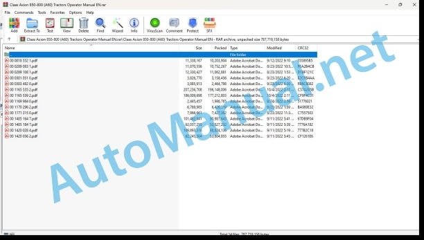
File List:
00 0018 552 1.pdf
00 0289 083 1.pdf
00 0289 108 1.pdf
00 0301 051 0.pdf
00 0303 482 0.pdf
00 1165 535 2.pdf
00 1165 559 2.pdf
00 1169 984 0.pdf
00 1170 296 2.pdf
00 1171 315 0.pdf
00 1405 164 7.pdf
00 1405 184 7.pdf
00 1420 028 4.pdf
00 1420 056 2.pdf
00 0018 552 1.pdf:
TELEMATICS Website
Table of contents
1 About this Concise Operator’s Manual
1.1 Notes on the manual
1.1.1 Validity of manual
1.1.2 Notes regarding the Concise Operator’s Manual
1.1.3 Notes on warranty
2 Safety
2.1 Intended use
2.1.1 Proper use
3 Product description
3.1 Overview and method of operation
3.1.1 TELEMATICS product variants
3.1.2 TONI (TELEMATICS on implements)
3.1.3 Fleet View
3.1.4 TELEMATICS basic
3.1.5 TELEMATICS advanced
3.1.6 TELEMATICS professional
3.1.7 TELEMATICS app
4 Operating and control elements
4.1 TELEMATICS overview
4.1.1 Illustration conventions of buttons and navigation elements
4.1.2 Symbols and colours
4.2 Menu structure
4.2.1 Start screen
4.2.2 TELEMATICS website site map
4.2.3 Main menu overview
4.2.4
4.2.5
4.2.6
00 0289 083 1.pdf:
CTIC 2800CTIC
Table of contents
1 Introduction
1.1 General information
1.1.1 Validity of manual
1.1.2 Information about this Operator’s Manual
1.1.3 Symbols and notes
1.1.4 Optional equipment
1.1.5 Maintenance information
1.1.6 Warranty information
1.1.7 Qualified specialist workshop
1.1.8 Spare parts and technical questions
1.2 Intended use
1.2.1 Intended use
1.2.2 Reasonably foreseeable misuse
2 Safety
2.1 Identifying warnings
2.1.1 Hazard signs
2.1.2 Signal word
2.2 Safety rules
2.2.1 Importance of Operator’s Manual
2.2.2 Optional equipment and spare parts
2.2.3 Danger due to damage to the tyre pressure control system
2.2.4 Technical condition
2.2.5 Complying with technical limit values
2.2.6 Keeping protective devices functional
2.2.7 Personal protective equipment
2.2.8 Dangers when driving on the road and on the field
2.2.9 Environmental protection and disposal
2.2.10 Noise can damage your health
2.2.11 Liquids under pressure
2.2.12 Compressed air
2.2.13 Hot surfaces
2.2.14 Maintenance work and repair work
2.2.15 Welding work prohibited
3 Product description
3.1 Package list
3.1.1 Delivery state
3.2 Overview and method of operation
3.2.1 Tyre pressure control system
3.3 Safety devices
3.3.1 Mechanical and electronic safety features
Pressure limitation
Automatic shut-down of control process
System behaviour when an air line is torn off
Manual operation
3.4 Identification plate and vehicle identification number
3.4.1 Identification plate of tyre pressure control system
4 Operating and display elements
4.1 Menu structure of CLAAS CTIC App
4.1.1 Start screen
4.1.2 Service menu
4.1.3 Working screen
Display elements and setting options on the working screen of CLAAS CTIC App
5 Technical specifications
5.1 Tyre pressure control system
5.1.1 Properties
5.1.2 Lubricants
6 Handling
6.1 Transport and storage
6.1.1 Transport
Compressor
6.1.2 Storage
7 Preparing the product
7.1 Putting into operation
7.1.1 Carry out prior to operation
Installing the tyre pressure control system
Preparing the iPad Mini for using the CLAAS CTIC App
Installing the software for controlling the tyre pressure control system
Workplace description
Fixing the iPad Mini
7.1.2 Performing putting into operation
8 Operation
8.1 Tyre pressure control system
8.1.1 Observe prior to operating the system
8.1.2 Determining the wheel loads
Fundamentals for determining wheel loads
Determining the wheel load on the front axle
Determining the wheel load on the rear axle
Determining the wheel load of the hitched implement
Example of how to calculate the wheel loads
8.1.3 Activating the tyre pressure control system
8.1.4 Deactivating the tyre pressure control system
8.1.5 Creating a profile
Compressor configuration
Select the tyres (manual volume input activated in the service menu)
Select the tyres (manual volume input deactivated in the service menu)
Entering the profile name
Defining set values for the towing vehicle
Harvesting mode OFF/ON
Defining set values for the trailer
Changing the created profile
Deleting a profile
8.1.6 Executing the profile
Fieldwork / road travel
Performing the control process
Slope stabilisation
Profile exit
9 Faults and remedies
9.1 Tyre pressure control system
9.1.1 Overview of possible problems with the tyre pressure control system
10 Maintenance
10.1 Maintenance interval overview
10.1.1 Every 10 operating hours or daily
10.1.2 Every 600 operating hours
10.1.3 Every 1200 operating hours or annually
10.1.4 Maintenance operations every 2400 operating hours
10.2 Tyre pressure control system
10.2.1 Cleaning and preserving the tyre pressure control system
10.2.2 Checking and cleaning the compressor air filter
Checking the air filter
Cleaning the air filter
10.2.3 Changing the air filter element
10.2.4 Checking the compressor oil level
10.2.5 Changing the compressor oil and oil filter
Changing the oil filter
Topping up oil
10.2.6 Replacing the compressor oil separator
10.3 Software update
10.3.1 Update of CLAAS CTIC App
11 Putting out of operation and disposal
11.1 General information
11.1.1 Putting out of operation and disposal
00 0289 108 1.pdf:
CTIC 2800 2.0CTIC 2.0
Table of contents
1 Introduction
1.1 General information
1.1.1 Validity of manual
1.1.2 Information about this Operator’s Manual
1.1.3 Symbols and notes
1.1.4 Optional equipment
1.1.5 Maintenance information
1.1.6 Warranty information
1.1.7 Qualified specialist workshop
1.1.8 Spare parts and technical questions
1.2 Intended use
1.2.1 Intended use
1.2.2 Reasonably foreseeable misuse
2 Safety
2.1 Identifying warnings
2.1.1 Hazard signs
2.1.2 Signal word
2.2 Safety rules
2.2.1 Importance of Operator’s Manual
2.2.2 Optional equipment and spare parts
2.2.3 Danger due to damage to the tyre pressure control system
2.2.4 Technical condition
2.2.5 Complying with technical limit values
2.2.6 Keeping protective devices functional
2.2.7 Personal protective equipment
2.2.8 Dangers when driving on the road and on the field
2.2.9 Environmental protection and disposal
2.2.10 Noise can damage your health
2.2.11 Pressurised fluids
2.2.12 Compressed air
2.2.13 Hot surfaces
2.2.14 Maintenance work and repair work
2.2.15 Welding work prohibited
3 Product description
3.1 Package list
3.1.1 Delivery state
3.2 Overview and method of operation
3.2.1 Tyre pressure control system
3.2.2 Tyre pressure control system
3.3 Safety devices
3.3.1 Mechanical and electronic safety features
Pressure limitation
System behaviour when an air line is torn off
Manual operation
3.4 Identification plates and identification numbers
3.4.1 Identification plate of tyre pressure control system
4 Operating and display elements
4.1 Monitor
4.1.1 Overview of operating screen
4.2
4.2.1
4.2.2
4.3
4.3.1
4.3.2
4.3.3
4.3.4
4.4
4.4.1
5 Technical specifications
5.1 Tyre pressure control system
5.1.1 Properties
5.1.2 Lubricants
6 Handling
6.1 Transport and storage
6.1.1 Transport
Compressor
6.1.2 Storage
7 Preparing the product
7.1 Putting into operation
7.1.1 Carry out prior to operation
Installing the tyre pressure control system
Workplace description
8 Operation
8.1 Tyre pressure control system
8.1.1 Observe prior to operating the system
8.1.2 Parking position
Removing the rotary transmission leadthrough cover
Removing the rotary transmission leadthrough cover
Moving the hose packages of front wheels to the parking position
Moving the hose package of the rear right wheel to the parking position
Moving the hose package of the rear left wheel to the parking position
Installing the cover on the rotary transmission leadthrough
Installing the cover on the rotary transmission leadthrough
Removing the rotary transmission leadthroughs
8.1.3 Parking position
Removing the rotary transmission leadthrough cover
Removing the rotary transmission leadthrough cover
Moving the hose packages of front wheels to the parking position
Moving the hose package of the rear right wheel to the parking position
Moving the hose package of the rear left wheel to the parking position
Installing the cover on the rotary transmission leadthrough
Installing the cover on the rotary transmission leadthrough
Removing the rotary transmission leadthroughs
8.1.4 Working position
Installing the rotary couplings
Moving the hose packages of front wheels to the working position
Moving the hose package of the rear right wheel to the working position
Moving the hose package of the rear left wheel to the working position
Installing the cover on the rotary transmission leadthrough
Installing the cover on the rotary transmission leadthrough
8.1.5 Working position
Installing the rotary couplings
Moving the hose packages of front wheels to the working position
Moving the hose package of the rear right wheel to the working position
Moving the hose package of the rear left wheel to the working position
Installing the cover on the rotary transmission leadthrough
Installing the cover on the rotary transmission leadthrough
8.1.6 Determining the wheel loads
Fundamentals for determining wheel loads
Determining the wheel load on the front axle
Determining the wheel load on the rear axle
Determining the wheel load of the hitched implement
Example of how to calculate the wheel loads
8.1.7 Activating the tyre pressure control system
8.1.8 Deactivating the tyre pressure control system
8.1.9 Creating a profile
Entering the profile name
Setting the tyre pressure values for the towing vehicle
Enabling the trailer
Trailer priority circuit
Setting the tyre pressure values for the trailer
Selecting the tyre size
8.1.10 Changing the profile
8.1.11 Deleting the profile
8.1.12 Activating the profile
Operating the profile in
Changing set values in
Operating the profile in
9 Faults and remedies
9.1 Tyre pressure control system
9.1.1 Overview of possible problems with the tyre pressure control system
10 Maintenance
10.1 Maintenance interval overview
10.1.1 Operating hours
10.1.2 Every 10 operating hours or daily
10.1.3 Every 600 operating hours
10.1.4 Every 1200 operating hours or annually
10.1.5 Maintenance work every 2400 operating hours
10.2 Tyre pressure control system
10.2.1 Cleaning and preserving the tyre pressure control system
10.2.2 Checking and cleaning the compressor air filter
Checking the air filter
Cleaning the air filter
10.2.3 Changing the air filter element
10.2.4 Cap
Removing
Installing
10.2.5 Checking the compressor oil level
10.2.6 Checking the compressor oil level
10.2.7 Changing the compressor oil and oil filter
Changing the oil filter
Topping up oil
10.2.8 Replacing the compressor oil separator
11 Putting out of operation and disposal
11.1 General information
11.1.1 Putting out of operation and disposal
00 0301 051 0.pdf:
PROFI CAM 3
Table of contents
1 Introduction
1.1 Notes on the manual
1.1.1 Validity of manual
1.1.2 Information about this Operator’s Manual
1.1.3 Symbols and notes
1.1.4 Optional equipment
1.1.5 Qualified specialist workshop
1.1.6 Maintenance information
1.1.7 Warranty notes
1.1.8 Spare parts and technical questions
1.2 Intended use
1.2.1 Intended use
1.2.2 Reasonably foreseeable misuse
2 Safety
2.1 Identifying warnings
2.1.1 Hazard signs
2.1.2 Signal word
2.2 Safety rules
2.2.1 Meaning of Operator’s Manual
2.2.2 Observing safety decals and warnings
2.2.3 Optional equipment and spare parts
3 Product description
3.1 Overview and method of operation
3.1.1 How the PROFI CAM works
3.2 Identification plates and identification number
3.2.1 Position of identification plates
3.2.2 Explanation of PROFI CAM identification plate
3.3 Information on the product
3.3.1 CE marking
4 Operating and control elements
4.1 Camera system
4.1.1 Camera system monitor
4.2 Menu structure
4.2.1 Main menu
4.2.2
4.2.3
4.2.4
4.2.5
4.2.6
5 Technical specifications
5.1 PROFI CAM
5.1.1 Monitor
5.1.2 Camera
5.1.3 Switch box
5.1.4 Degree of protection against foreign bodies and water
6 Preparing the product
6.1 Shutting down and securing the machine
6.1.1 Switching off and securing the machine
6.2 Prior to operation
6.2.1 Carry out prior to operation
6.2.2 Installing the sun protection
6.2.3 Aligning the camera
6.2.4 Connecting the camera electrics
7 Operation
7.1 Monitor
7.1.1 Switching on the monitor
7.1.2 Calling up the menu
7.1.3 Setting a menu item
7.1.4 Setting the image orientation
7.1.5 Setting automatic screen darkening
7.1.6 Image mirroring
7.1.7 Setting the trigger view
7.1.8 Setting the follow-up time for trigger view
7.1.9 Setting the display mode
7.1.10 Activating/deactivating a display mode
8 Faults and remedies
8.1 Electrical and electronic system
8.1.1 Overview of problems on PROFI CAM camera system
8.1.2 Replacing the switch box fuse
9 Maintenance
9.1 Maintenance intervals
9.1.1 Every 10 operating hours or daily
9.2 Camera system
9.2.1 Checking the camera system for dirt
9.2.2 Cleaning the camera
9.2.3 Cleaning the switch box
9.2.4 Cleaning the monitor
10 Placing out of operation and disposal
10.1 General Information
10.1.1 Putting out of operation and disposal
11 Technical terms and abbreviations
11.1 Abbreviations
11.1.1 Units
11.1.2 Abbreviations
11.1.3 Technical terms
00 0303 482 0.pdf:
PROFI CAM 4
Table of contents
1 Introduction
1.1 Notes on the manual
1.1.1 Validity of manual
1.1.2 Information about this Operator’s Manual
1.1.3 Symbols and notes
1.1.4 Optional equipment
1.1.5 Qualified specialist workshop
1.1.6 Maintenance information
1.1.7 Notes on warranty
1.1.8 Spare parts and technical questions
1.2 Intended use
1.2.1 Intended use
1.2.2 Reasonably foreseeable misuse
2 Safety
2.1 Identifying warnings
2.1.1 Hazard signs
2.1.2 Signal word
2.2 Safety rules
2.2.1 Meaning of Operator’s Manual
2.2.2 Structural changes
2.2.3 Optional equipment and spare parts
2.2.4 Operation only following proper putting into operation
2.2.5 Technical status
2.2.6 Respecting technical limit values
Respecting technical limit values
2.2.7 Hazards when driving on roads and fields
3 Product description
3.1 Overview and method of operation
3.1.1 How the PROFI CAM works
3.2 Identification plates and identification number
3.2.1 Identification plates
3.3 Information on the product
3.3.1 CE marking
4 Operating and display elements
4.1 Camera system
4.1.1 Camera system monitor
4.1.2 CEBIS
4.2 Menu structure
4.2.1 Main menu
4.2.2
4.2.3
4.2.4
4.2.5
4.2.6
5 Technical specifications
5.1 PROFI CAM
5.1.1 Monitor
5.1.2 Camera
5.1.3 Switch box
6 Preparing the product
6.1 Switching off and securing the machine
6.1.1 Switching off and securing the machine
6.2 Prior to putting into operation
6.2.1 Carry out prior to operation
6.2.2 Installing the sun protection
6.2.3 Aligning the camera
7 Operation
7.1 Monitor
7.1.1 Switching on the monitor
7.1.2 Calling up the menu
7.1.3 Setting a menu item
7.1.4 Setting the image orientation
7.1.5 Setting automatic screen darkening
7.1.6 Image mirroring
7.1.7 Setting the trigger view
7.1.8 Setting the follow-up time for trigger view
7.1.9 Setting the display mode
7.1.10 Activating/deactivating a display mode
8 Faults and remedies
8.1 Electric and electronic system
8.1.1 Overview of problems on PROFI CAM camera system
9 Maintenance
9.1 Maintenance intervals
9.1.1 Every 10 operating hours or daily
9.2 Camera system
9.2.1 Checking the camera system for dirt
9.2.2 Cleaning the camera
9.2.3 Cleaning the switch box
9.2.4 Cleaning the monitor
10 Putting out of operation and disposal
10.1 General information
10.1.1 Putting out of operation and disposal
11 Technical terms and abbreviations
11.1 Abbreviations
11.1.1 Units
11.1.2 Abbreviations
11.1.3 Technical terms
00 1165 535 2.pdf:
AXION 850-840-830-810-800HEXASHIFT-CEBIS
Table of contents
1 Introduction
1.1 Notes on the manual
1.1.1 Validity of the operator’s manual
1.1.2 Using the operator’s manual
Important information concerning this operator’s manual
Structure based on tractor sub-assemblies
Search and find
Direction indications
Specific terminology
Optional and additional equipment
1.1.3 Symbols and instructions
Text and illustrations
Highlighting dangers and warnings
1.1.4 Optional equipment
1.1.5 Software developments
1.1.6 Qualified specialist workshop
1.1.7 Technical information
1.1.8 Notes on maintenance
1.1.9 Notes on warranty
1.1.10 Spare parts and technical questions
1.1.11 Transferring the tractor to a third party
1.2 Intended use
1.2.1 Appropriate use
1.2.2 Inappropriate use
2 Safety
2.1 Identifying warnings
2.1.1 Hazard signs
2.2 Safety rules
2.2.1 Checking the condition of the tractor
2.2.2 High risk areas
2.2.3 Instructor’s seat
2.2.4 Applications with front loaders
2.2.5 European regulations
2.2.6 Safety and accident prevention instructions
2.2.7 Driving the tractor
2.2.8 Protection provided by the tractor cab
Safety structure of the tractor cab
Polluted environment
Tractor cab category
Category 2 (protection against dust)
Category 3 (protection against dust and aerosols)
2.2.9 Climbing into the cab and out of the tractor.
Climbing into the tractor
Climbing out of the tractor
2.2.10 Passenger seat
2.2.11 Precautions to be taken before starting up
2.2.12 Hitching implements
2.2.13 Adjustments and maintenance work
Special notes on mounting the tractor on axle stands
2.2.14 Using the front and rear power take-off
2.2.15 Fuel
2.2.16 Engine coolant
2.2.17 Air conditioning
2.2.18 Electrical system
2.2.19 Behaviour in case of voltage flash-over from overhead lines and when lightning strikes
2.2.20 Forest applications
2.2.21 Stationary working
2.2.22 Implements operating at great depth
2.3 Safety decals on the tractor
2.3.1 General advice regarding the safety markings
2.3.2 Layout of safety decals
2.3.3 Warning symbols
2.4 Safety devices
2.4.1 Windscreen hammer
2.4.2 Wheel chocks
2.4.3 Extinguisher mounting bracket
2.4.4 First aid kit
3 Tractor description
3.1 Overview
3.1.1 Front left-hand view
3.1.2 Rear right-hand view
3.2 Identification plates and vehicle identification number
3.2.1 Tractor identification plate
Tractor identification number
3.2.2 Engine identification plate
3.2.3 Front axle identification plate
3.2.4 Pick-up hitch identification plate
3.2.5 Front power take-off identification plate
3.2.6 Cab identification plate
3.2.7 Additional cab identification plate
3.3 Information on the tractor
3.3.1 Coolant
3.3.2 Lifting points
3.3.3 Tightening the wheels
3.3.4 Checking the immobilisation of the load
3.3.5 Electrical and electronic system
3.3.6 Emergency exit
3.3.7 Automatic electrical circuit breaker
3.3.8 Engine bonnet
3.3.9 Lubricating the front linkage and front axle
3.3.10 Lubricating the rear hitch
3.3.11 Lubricating the pick-up hitch
4 Operating and display elements
4.1 Cab and operator’s platform
4.1.1 Multifunction armrest
4.1.2 Multifunction armrest
4.1.3 CMOTION multifunction handle
4.1.4 Cab top
4.1.5 Right-hand cab pillar
4.1.6 Dashboard
4.1.7 Instrument panel module
4.1.8 Main display
4.1.9 Manual air conditioning
4.1.10 Automatic air conditioning
4.1.11 Control panel for work lights and warning beacon
4.1.12 Driving position control levers
Indicator lights and horn
Screen wipers and washers
4.1.13 Right-hand console electrical sockets
4.2 Hydraulic system
4.2.1 Hydraulic controls
4.3 Electric and electronic system
4.3.1 External controls
Rear external controls
Front external controls
4.3.2 External electrical sockets
Rear external electrical sockets
Front external electrical sockets
4.4 CEBIS
4.4.1 General information about the CEBIS
4.4.2 Overview of the CEBIS terminal
4.4.3 Introduction to the user interface
Work phase zone
Structure of the
4.4.4 Work phases
Road mode
Field mode
ISO Terminal mode
4.4.5 Using the touch screen
4.4.6 Using the buttons
4.4.7 Display conventions
4.4.8 Using the keyboard or number keypad
4.4.9 Editing parameter settings
Rotary selector
4.4.10 Error message
4.4.11 Structure of the CEBIS menu
4.4.12
4.4.13
4.4.14
4.4.15
4.4.16
4.4.17
4.4.18
4.4.19
4.4.20
4.4.21
4.4.22
4.4.23
5 Technical specifications
5.1 AXION 800
5.1.1 Tractor dimensions
5.1.2 Weight
5.1.3 Engine
5.1.4 Gearbox
5.1.5 Travel speeds
Standard range
Creeper gear range
5.1.6 Rear axle
5.1.7 Front axle
Suspended front axle (with brakes)
Suspended front axle (without brakes)
Rigid front axle (without brakes)
5.1.8 Table of front track widths
Rims with fixed wheel disc
Rims with variable wheel disc
5.1.9 Table of rear tracks
Rim with fixed wheel disc – Flanged shafts
Fixed disc rim – Minimum track with smooth shafts
Fixed disc rim – Maximum track with 2.5 metre smooth shafts
Fixed disc rim – Maximum track with 3 metre smooth shafts
5.1.10 Table of rear track widths with twinning spacers
Fixed disc rim – Track with 2.5 metre smooth shafts
Fixed disc rim – Track with 3-metre smooth shafts
5.1.11 Tyre combinations
5.1.12 Tyre inflation pressure
Rear tyres
Front tyres
5.1.13 Brakes
5.1.14 Direction
5.1.15 Rear linkage
Rear linkage with short lower connecting rods
Rear linkage with long lower connecting rods
5.1.16 Front linkage
5.1.17 Rear hitches
5.1.18 Rear power take-off
5.1.19 Front power take-off
5.1.20 Main hydraulic circuit
5.1.21 Main hydraulic circuit
5.1.22 Electrohydraulic control valve combinations
5.1.23 Electrical circuit
5.1.24 Cab specifications
Driver’s exposure to noise level (according to annex XIII of the delegated regulation 1322/2014)
Passers-by exposure to noise level (according to annex III of delegated regulation 2015/96)
5.1.25 Seat vibration level
5.1.26 Ballast
5.1.27 Maximum authorised tow weights
5.1.28 Load capacities
5.2 Operating utilities
5.2.1 Lubricants and hydraulic oils
5.2.2 Engine coolant
5.2.3 Air conditioning refrigerant
6 Tractor preparation
6.1 Securing the tractor
6.1.1 Parking and securing the tractor
6.1.2 Securing the tractor
6.2 Prior to putting into operation
6.2.1 Preparing for initial commissioning
6.2.2 Preparing for commissioning
6.2.3 Hitching and connecting the implement
6.3 Engine
6.3.1 Fuel
Quality requirement
Special notes on biofuels
Handling fuel
6.3.2 Urea solution
Using urea solution
Urea solution purity and standard
Storing urea solution in tanks or containers
6.3.3 Topping up the tractor
Topping up
Topping up the urea solution
6.3.4 Preparing the engine for cold starting
6.4 Frame
6.4.1 Setting the front axle track
6.4.2 Adjusting the rear axle track
Flanged shafts
Smooth shafts
Smooth shafts
6.4.3 Adjusting the steering stops
Fitting the jack
Fitting axle stands
Adjusting the steering stops
6.4.4 General information about the tyres
6.4.5 Tyre inflation pressure
Effect on soil compaction
Effect on consumption
With twin wheels
6.4.6 Specifications
Load index
Speed symbol
6.4.7 Fitting twin wheels on the tractor
6.4.8 Fitting twin wheels on smooth shafts
Smooth shafts
Smooth shafts
6.4.9 Fitting twinning spacers
AXION 810-800
AXION 830
AXION 850-840
6.4.10 Using wheel chocks
6.5 Brake
6.5.1 Coupling the brake pedals
6.5.2 Trailer hydraulic brake
6.5.3 Trailer air brake
6.6 Steering
6.6.1 Steering column
6.6.2 Connect another manufacturer’s guidance system to the steering interface
6.7 Rear power lift
6.7.1 Hitching/unhitching an implement
Hitching recommendations
Hitching
Unhitching
6.7.2 Axle stands
6.7.3 Axle stands
Adjusting the length of the axle stands
Mechanical floating position
6.7.4 Mechanical top link
6.7.5 Hydraulic top link
6.7.6 Stabilisers
Mechanical stabilisers
Self-locking stabilisers
6.7.7 Automatic hitches
6.7.8 External controls
6.8 Front power lift
6.8.1 Hitching/unhitching an implement
Hitching recommendations
Hitching
Unhitching
6.8.2 Mechanical top link
6.8.3 Positioning the lower links
6.8.4 Automatic hitches
6.8.5 External controls
6.9 Rear power take-off
6.9.1 Hitching and unhitching an implement
Connecting and disconnecting the rear power take-off universal drive shaft
Hitching
Unhitching
6.9.2 Replacing the rear power take-off end fitting
6.10 Front power take-off
6.10.1 Hitch and unhitch an implement
6.10.2 Connecting/disconnecting the front power take-off
Disconnecting the front power take-off from the engine
Connecting the front power take-off to the engine
6.11 Hitch
6.11.1 Recommendations
6.11.2 Calculation of the maximum tow load
6.11.3 Hitching and unhitching an implement
Hitching
Unhitching
6.11.4 Hitching bolt
6.11.5 Clevis drawbars
Rotating clevis pin
Automatic clevis
Clevis ball
CUNA non-rotary clevises
6.11.6 Swinging drawbar
Positioning the swinging drawbar laterally
Positioning the swinging drawbar longitudinally
Maximum implement movement
Safety device
Tightening the clevis on the swinging drawbar
Hitch a tool with the Drop Pin swinging drawbar
6.11.7 Eye bolt catch plate
6.11.8 Tow hook
Forced steering
6.11.9 Replacing the end of the pick-up hitch
6.12 Rear hydraulic system
6.12.1 Rear pressure take-offs
Connecting the pressure take-offs
Disconnecting the pressure take-offs
6.12.2 Connect an implement to the Power-Beyond
6.13 Front hydraulic system
6.13.1 Supply the front hydraulic pressure taps (tractors with two front pressure taps)
6.13.2 Connecting an implement to the front hydraulic pressure taps
6.14 Electric and electronic system
6.14.1 Adjust the dipped beam headlights
Engine bonnet dipped beam headlights
Cab dipped beam headlights
6.14.2 Connect a camera to the CEBIS terminal
6.15 Cab and operator’s platform
6.15.1 Adjusting the cab suspension
6.15.2 Adjusting the external rear-view mirrors
Adjusting the external rear-view mirror lateral position
Adjusting the external rear-view mirror lateral position (manual adjustment)
Adjusting the rear-view mirror lateral position (electronic adjustment)
Defrosting the external rear-view mirrors
6.15.3 Adjusting the mechanical suspension seat
6.15.4 Adjusting the Grammer pneumatic suspension seat
6.15.5 Adjusting the Sears air suspension seat
6.15.6 Adjusting the Sears semi-active air suspension seat
6.15.7 Adjusting the active pneumatic suspension seat
6.15.8 Adjusting the Grammer semi-active air suspension seat with adjustable seat back
6.15.9 Passenger seat
6.15.10 Multifunction armrest
6.15.11 Positioning the CEBIS screen
6.15.12 Mobile storage box (depending on equipment)
6.15.13 Storage compartment
6.15.14 Routing the cables of a control box
6.15.15 Installing a control unit in the cab
6.15.16 Installing a control unit in the cab
6.15.17 Supports for cab front lights
6.16 Assembly parts and machine body
6.16.1 Open the engine bonnet
6.16.2 Adjusting the position of the step bottom rung
6.16.3 Ballast
6.16.4 Ballast water
6.16.5 Balancing the tractor with mounted implements
Summary table
6.16.6 Weight on the front linkage
6.16.7 Fitting and removing the front weights
Removable weights
Basic front single unit weight
Additional front single unit weight
6.16.8 Fitting removable weights
6.16.9 Fitting the front ballast weight
6.16.10 Rear wheel weights
Wheel weights for 42 rims
Wheel wei
John Deere Repair Technical Manual PDF
John Deere Repair Technical Manual PDF
John Deere Transmission Control Unit Component Technical Manual CTM157 15JUL05
John Deere Repair Technical Manual PDF
John Deere Repair Technical Manual PDF
John Deere Repair Technical Manual PDF
John Deere Diesel Engines POWERTECH 2.9 L Component Technical Manual CTM126 Spanish
John Deere Repair Technical Manual PDF
John Deere Repair Technical Manual PDF
John Deere 18-Speed PST Repair Manual Component Technical Manual CTM168 10DEC07
John Deere Repair Technical Manual PDF
John Deere Application List Component Technical Manual CTM106819 24AUG20
John Deere Repair Technical Manual PDF

