Claas Axion 960-930 Terratrac (A42) Tractors Repair Manual EN
$100.00
- Model: Axion 960-930 Terratrac (A42) Tractors
- Type Of Manual: Repair Manual
- Language: EN
- Format: PDF(s)
- Size: 190 MB
File List:
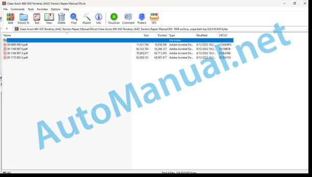
00 0000 000 0.pdf
00 1169 987 0.pdf
00 1169 987 X.pdf
00 1173 803 X.pdf
00 0000 000 0.pdf:
GEARBOX CMATIC TMG 45
Table of contents
Introduction
General information
Using this repair manual
Validity of this repair manual
General repair instructions
Technical specifications
Cause of damage
Spare parts
Diesel engine
Alternator
Welding work
Drive belt/drive chains
Tapered ring assemblies
Self-locking bolts with microencapsulated glue
Threadlock
Lock collar bearing
Collet bearing
Threaded unions with cutting rings on the hydraulic hoses
Threaded unions with progressive rings on the hydraulic hoses
Threaded double flare unions on the hydraulic hoses
Flexible hydraulic pipes
Pipe routing
Advice for economical repairs
Tightening torques
Tightening torques for NF E25-030-1 2007-12-01 standard metric threads
Tightening torques for CLAAS CN 020 225 standard hydraulic connections
Tightening torques for hydraulic threaded unions and air conditioning threaded unions with sealing cone and DIN 3865 O-ring
Tightening torques for DIN 3901 hydraulic threaded unions
Tightening torques for ISO 6149-2/ISO 11926-2 (3) adjustable hydraulic threaded unions
Tightening torques for hydraulic swivel threaded unions
Tightening torques for DIN 7643 hollow bolts
Technical specifications
Lubricants
Signal words and symbols
02 Gearbox / Clutch / Universal drive shaft
0202 Complete component
Speed sensors, speed transmitter, inductive sensor and pressure sensors
Removing the pressure filter
Removing hydraulic control unit
Dismantling hydraulic control unit
Removing hydraulic control unit
Dismantling hydraulic control unit
Removing pressure tube and pump
Removing the filter (hydrostatic unit)
Removing shaft seal
Mounting transmission on assembly truck
Removing central shaft
Dismantling central shaft
Separating clutch housing from intermediate housing
Removing shifting drum
Removing spur gear and ball bearing
Dismantling planetary drive (P1)
Dismantling planetary drive (P2)
Dismantling planetary drive (P3)
Dismantling clutch (K1/K2)
Lifting off splined tube
Dismantling clutch and planetary drive (K3/K4 and P4)
Dismantling ring gear
Removing brake
Dismantling brake
Removing the KR clutch
Dismantling KR clutch
Removing and dismantling central shaft
Removing KV clutch
Dismantling clutch KV
Removing and dismantling intermediate gear
Removing and dismantling spur gears
Removing and dismantling shaft and spur gears (hydrostatic drive)
Removing shaft and spur gear (pump drive)
Removing and dismantling drive gear (output)
Fixing clutch housing in the assembly truck
Removing and dismantling tube
Removing and dismantling the hydrostat
Removing tube and screw-in sleeves
Removing wiring harness
Removing and dismantling intermediate gears and spur gear (hydrostat output)
Fixing clutch housing into assembly truck and installing screw plugs
Assembling and installing spur gear and intermediate gears (hydrostatic output)
Installing wiring harness
Installing screw-in sleeves and tube
Assembling and installing hydrostat
Assembling and installing drive gear (output)
Installing spur gear and shaft (pump drive)
Assembling and installing spur gears
Installing spur gears and shaft (hydrostatic drive)
Assembling and installing intermediate gear
Assembling clutch KV
Installing clutch KV
Assembling and installing central shaft
Assembling clutch KR
Installing clutch KR
Assembling brake
Installing brake
Assembling clutch and planetary drive (K3/K4 and P4)
Assembling clutch (K1/K2)
Assembling planetary drive (P3)
Assembling planetary drive (P2)
Assembling planetary drive (P1)
Assembling the shifting drum
Assembling ring gear
Installing shifting drum
Installing clutch housing on the intermediate housing
Assembling and installing tube and screw plugs
Assembling central shaft
Installing central shaft
Depositing transmission
Fitting shaft sealing ring
Installing the filter (hydrostatic unit)
Installing pump and pressure tube
Assembling hydraulic control unit
Installing hydraulic control unit
Assembling hydraulic control unit
Installing hydraulic control unit
Mounting the pressure filter
Installing pressure sensors, inductive sensor, speed transmitter and speed sensors
Installing screw plugs
00 1169 987 0.pdf:
AXION 960-930 TERRA TRACStage IV
Table of contents
CCN (CLAAS Component Number)
Introduction
General information
Using this repair manual
Validity of this repair manual
General repair instructions
Technical specifications
Cause of damage
Spare parts
Diesel engine
Alternator
Welding work
Drive belt/drive chains
Tapered ring assemblies
Self-locking bolts with microencapsulated glue
Threadlock
Lock collar bearing
Collet bearing
Threaded unions with cutting rings on the hydraulic hoses
Threaded unions with progressive rings on the hydraulic hoses
Threaded double flare unions on the hydraulic hoses
Flexible hydraulic pipes
Pipe routing
Advice for economical repairs
Tightening torques
Tightening torques for NF E25-030-1 2007-12-01 standard metric threads
Tightening torques for CLAAS CN 020 225 standard hydraulic connections
Tightening torques for hydraulic threaded unions and air conditioning threaded unions with sealing cone and DIN 3865 O-ring
Tightening torques for DIN 3901 hydraulic threaded unions
Tightening torques for ISO 6149-2/ISO 11926-2 (3) adjustable hydraulic threaded unions
Tightening torques for hydraulic swivel threaded unions
Tightening torques for DIN 7643 hollow bolts
Technical specifications
Lubricants
General information
Important
Warning and danger markings
General safety advice and accident prevention regulations
First aid measures
Leaving the tractor
Adjustment and maintenance work
Risk of injury from hydraulic fluid
Air conditioning
Accumulator
Battery isolating switch
Place the tractor on axle stands
Stopping the tractor
01 Engine
0102 Complete component
Coupling the front chassis to the engine
Technical specifications
0110 Engine housing
Cylinder block
Dimensional specifications
Timing cover
Technical specifications
Preparation for work
Stiffener panel
Technical specifications
Preparation for work
Technical specifications
Preparation for work
Special tool
0115 Engine unit
Technical specifications
Dimensional specifications
Preparation for work
Special tool
Removing the liners
Cleaning
Visual inspection
Checking the liner flange
Checking the inner diameter of the liner
Fitting and checking the protrusion of the liner
Connecting rod and piston assembly
Technical specifications
Dimensional specifications
Special tool
Removing the conrod and piston assembly
Dismantling
Checks and measurements
Piston pin
Piston rings
Connecting rod and half-shells
Assembly
Fitting the connecting rod and piston assembly
Crankshaft and bearing shells
Technical specifications
Preparation for work
Dimensional specifications
Removing the crankshaft
Checks and measurements
Journals and crank pins
Procedure for selecting connecting rod and bearing half-shells
Determining the diameter class of the bearings on the cylinder block
Determining the diameter class of journals and crank pins
Selecting the colour of the bearing half-shells (nominal or standard diameter journals)
Selecting the colour of the bearing half-shells (journals modified to – 0.127 mm)
Determining the diameter class of the housings on the connecting rod
Selecting the colour of the connecting rod half-shells (nominal or standard diameter crank pins)
Selecting the colour of the connecting rod bearing half-shells (modified crank pins to – 0.127 mm)
Selecting the colour of the connecting rod bearing half-shells (crank pins modified to – 0.254 mm)
Selecting the colour of the connecting rod bearing half-shells (crank pins modified to – 0.508 mm)
Fitting the crankshaft
Replacing the crankshaft pinion
Checking the crankshaft lateral play
Crankshaft bearing seals
Technical specifications
Preparation for work
Special tool
Remo crankshaft rear bearing seal
Fitting the crankshaft rear bearing seal
Removing the cr front bearing seal
Fitting the crankshaft front bearing seal
Crankshaft pulley and torsional absorber
Technical specifications
Flywheel
Technical specifications
Special tool
Dismantling
Assembly
0120 Cylinder head / Valves / Idler gear
Cylinder head
Technical specifications
Flatness of the cylinder head
Cylinder head cover
Technical specifications
Dimensional specifications
Special tool
Cleaning and checking the valves
Checking the valve springs
Checking and replacing the valve seats
Fitting the valves
Checking the valve withdrawal
Valve rockers – Rods
Technical specifications
Dimensional specifications
Special tool
Adjusting the valve clearance
Camsha and bearing shells
Dimensional specifications
Special tool
Checks and measurements
Bearing journals
Cam operating height
Ring and journal housings in the cylinder head
Removing the camshaft rings
Fitting the camshaft rings
Checking the clearance between the timing pinion teeth
Technical specifications
Preparation for work
Special tool
Adjusting the clearance between teeth on the high-pressure pump pinion
Adjusting the clearance between the teeth on the intermediate pinion
Setting the timing
Technical specifications
Special tool
Camshaft timing
Setting the phonic wheel
Removing the timing setting tools
0125 Injection / Fuel system
Main tank
Technical specifications
Special tool
Secondary tank
Technical specifications
Special tool
High pressure pump
Technical specifications
Removing the high-pressure pump
Fitting the high-pressure pump
Removing the supply pump
Fitting the supply pump
Removing the fuel pressure solenoid valve Y489
Fitting the fuel pressure solenoid valve Y489
Fuel pre-filter and cooler
Technical specifications
Injection pipes
Technical specifications
Injector
Technical specifications
Preparation for work
Special tool
Removing an injector
Fitting an injector
Removing all injectors
Fitting all of the injectors
0130 Lubricating oil system
Oil pump
Technical specifications
Dimensional specifications
Oil pressure regulation valve
Technical specifications
Dimensional specifications
Oil filter
Technical specifications
Oil cooler
Technical specifications
Preparation for work
0135 Cooling system
Fan and belts
Technical specifications
Preparation for work
Special tool
Removing the fan
Fitting the fan
Removing the fan pulley
Fitting the fan pulley
Engine water radiator
Technical specifications
Expansion chamber
Technical specifications
Water pump
Technical specifications
Water reservoir
Technical specifications
Thermostat
Technical specifications
Engine coolant heater
Technical specifications
Preparation for work
0140 Exhaust system
Turbocharger
Technical specifications
Preparation for work
Inspecting the turbocharger
Compressor inspection
Turbine inspection
Exhaust gas flap
Technical specifications
Preparation for work
Exhaust manifold
Technical specifications
Preparation for work
0145 Air intake
Air filter
Technical specifications
Air cooler
Technical specifications
Preparation for work
Intake and preheating manifold
Technical specifications
0150 Engine attachment parts
Electric starting motor
Technical specifications
Alternator
Technical specifications
0155 Engine control
Technical specifications
Fitting advice
Engine control module
Technical specifications
Accelerator pedal
Technical specifications
0165 Exhaust gas aftertreatment
Technical specifications
Urea supply unit
Technical specifications
Preparation for work
Special tool
Removing the urea supply unit
Fitting the urea supply unit
Urea tank
Technical specifications
Urea injector
Technical specifications
Preparation for work
Cleaning
“SCR” and “CUC” catalytic converter unit
Technical specifications
Special tool
Removing the “SCR” and “CUC” catalytic converter unit with its support
Fitting the “SCR” and “CUC” catalytic converter unit with its support
catalytic converter unit without its support
Fitting the “SCR” and “CUC” catalytic converter diesel oxidation catalyst
Technical specifications
02 Gearbox / Clutch / Universal drive shaft
0202 Complete component
Steps for removal
Technical specifications
Coupling the gearbox to the engine
Technical specifications
Special tool
Coupling the gearbox to the rear axle
Technical specifications
Preparation for work
Special tool
0210 Oscillation damper
Transport damper
Technical specifications
Preparation for work
0218 Clutch control
Clutch pedal
Technical specifications
0228 Reverser control
Clutchless reverser lever
Technical specifications
0230 Mechanical gearbox
Gearbox input shaft seal
Technical specifications
Special tool
0232 Hydraulical gearbox
Protective sieve
Technical specifications
0238 Gearbox control
Gearbox sensors
Tespecifications
Preparation for work
System control unit
Technical specifications
Special tool
Dismantling
Assembly
Clutch control unit
Technical specifications
Special tool
Dismantling
Assembly
0240 Rear axle housing
Rear axle casing
Technical specifications
Preparation for work
Connecting casing
Technical specifications
Preparation for work
Special tool
Dismantling
Assembly
0242 Differential
Drive pinion
Technical specifications
Preparation for work
Special tool
Removing the transfer case
Removing the drive pinion
Adjusting the drive pinion’s conical distance
Preloading the drive pinion bearings
Checking the drive pinion drag torque
Fitting the drive pinion
Fitting the transfer case
Differential
Technical specifications
Preparation for work
Removing the differential
Dismantling
Assembly
Adjusting the clearance between teeth on the crown gear
Setting the differential bearing preload
Checking the settings
Fitting the differential
0252 Electro-hydraulical front axle drive
Four-wheel-drive shaft
Technical specifications
Special tool
Setting the c bearing preload
Four-wheel-drive clutch
Technical specifications
Special tool
Removing the four-wheel drive clutch
Disassembling the four-wheel drive clutch
Auxiliary tool
Assembling the four-wheel drive clutch
Adjusting the play b
Fitting the four-wheel drive clutch
Removing the inlet ring
Fitting the inlet ring
0255 Gearbox cooling system
Accessories pump
Technical specifications
Thermostatic valve
Thermostatic valve
0260 Universal drive shaft
Transmission shaft
Technical specifications
Preparation for work
03 Chassis
0325 Front steering drive axle
Decompressing the front axle suspension circuit
Technical specifications
Decompressing the circuit
Recommissioning the circuit
Complete front axle
Technical specifications
Preparation for work
Steering angle sensor
Technical specifications
Preparation for work
Calibration
Front axle position sensor (DANA)
Technical specifications
Preparation for work
Special tool
Adjustment
Wheel hubs and reducer
Technical specifications
Preparation for work
Special tool
Dismantling
Assembly
Wheel pivot
Technical specifications
Preparation for work
Special tool
Assembly with steering angle sensor
Dismantling
Assembly
Adjustment
Assembly with steering angle sensor
Drive pinion
Technical specifications
Preparation for work
Special tool
Adjusting the conical distance
Setting the bearing preload
Differential
Technical specifications
Preparation for work
Special tool
Dismantling
Assembly
Adjustment
0355 Track roller unit
Caterpillar track assembly
Overview
Technical specifications
Preparation for work
Special tool
Tyre tread
Technical specifications
Special tool
Removing the tyre tread
Fitting the tyre tread
Adjusting the tyre tread
Driving wheel and tensioning wheel
Technical specifications
Removing the wheels
Fitting the wheels
Changing the wheel pads
Support wheel
Technical specifications
Draining the support wheels
Technical specifications
04 Brake
0405 Service brake
Service brake
Technical specifications
Preparation for work
Auxiliary tool
Removing the service brake piston
Fitting the service brake piston
Adjusting the service brake piston play compensation system
Service brake sealing test
Brake pedals and valve
Technical specifications
Decompressing the brake circuit
Technical specifications
Cut-out relay
Technical specifications
Replacing the cut-out relay filter 1033.
Service brake accumulators
Technical specifications
Bleeding the brake circuit
Technical specifications
Bleeding the brake circuit
Brake test
0415 Parking brake
Handbrake control
Technical specifications
Adjusting the handbrake clearance
05 Steering
0505 Steering
Steering unit and column
Technical specifications
Removing the steering column
Fitting the steering column
Steering actuator
Technical specifications
Preparation for work
Dismantling
Assembly
Emergency steering block
Technical specifications
Emergency steering pump
Technical specifications
Preparation for work
Adjusting the front axle alignment
Technical specifications
Preparation for work
Adjusting the front axle alignment
0510 Automatic steering
GPS antenna
Technical specifications
06 Lift device
0605 Rear power lift
Rear linkage spool valve
Technical specifications
Technical specifications
Special tool
Linkage arm
Technical specifications
Preparation for work
Lift cylinder
Technical specifications
0610 Front power lift
Front linkage
Technical specifications
Preparation for work
Lift cylinder
Technical specifications
Preparation for work
Repairing the cylinder
07 Hitching device
0705 Coupling frame
Ladder hitch
Technical specifications
Forced steering ball joint(s)
Technical specifications
08 Drives
0802 Rear PTO
Rear power take-off
Technical specifications
Preparation for work
Dismantling
Output shaft adjustment
Input shaft timing
Rear power take-off sensors
Technical specifications
Preparation for work
0804 Front PTO
Front power take-off
Technical specifications
Preparation for work
09 Hydraulic system
0910 Pumps
Feed pump on 220 and 150 l/min circuit
Technical specifications
Preparation for work
Hydraulic pump (variable capacity 220 l/min)
Technical specifications
Preparation for work
Hydraulic pump (variable capacity 150 l/min)
Technical specifications
Preparation for work
0920 Valves
Booster feed plate on 220 and 150 l/min circuit
Technical specifications
Special tool
Feed plate for the variable capacity pump on the 220 l/min circuit
Technical specifications
Preparation for work
Special tool
For tractors equipped with pneumatic brakes
For tractors equipped with pneumatic brakes
Feed plate for the variable capacity pump on the 150 l/min circuit
Technical specifications
Preparation for work
Special tool
Priority valve on 220 l/min circuit
Technical specifications
Priority valve on 150 l/min circuit
Technical specifications
Rear auxiliary control valves
Technical specifications
Front auxiliary control valves
Technical specifications
10 Electrical / Electronic equipment
1005 Power supply
Battery tray
Technical specifications
1010 Central electrics
Fuse and relay board (PRF)
Technical specifications
Auto 5 board (PA5)
Technical specifications
UBM board
Technical specifications
Electronic adaptation board (PAE)
Technical specifications
1012 Modules / sensors
Auto 5 module
Technical specifications
UBM module
Technical specifications
Radar sensor
Technical specifications
1030 Board computer / Indicators
RHP rear linkage control panel
Technical specifications
Dashboard module
Technical specifications
1035 Operation / Multifunction control lever
CEBIS multifunction armrest
Multifunction armrest module technical specifications
Multifunction armrest support technical specifications
Preparation for work
CEBIS multifunction armrest support
Technical specifications
CEBIS terminal support
Technical specifications
Lower trim (CEBIS)
Technical specifications
Auxiliary tool
Position of the harnesses and mounting collars (CEBIS)
Special tool
Position of A100 module connectors (CEBIS)
C060 electrohydraulic joystick (CEBIS)
Technical specifications
Special tool
CMOTION C001 multifunction handle (CEBIS)
Technical specifications
Preparation for work
Special tool
B110 Direction lever position sensor – CEBIS
Technical specifications
Special tool
B154 Engine speed adjustment sensor (CEBIS)
Technical specifications
Special tool
Control valve B341, B342, B343 and B344 controls (CEBIS)
Technical specifications
Preparation for work
Special tool
Dismantling
Assembly
Rear (R052) and front (R053) linkage position setting potentiometers (CEBIS)
Technical specifications
Special tool
For the rear linkage position setting potentiometer 52
For the front linkage position setting potentiometer R053
Front (S113) and rear (S114) power take-off on/off swches (CEBIS)
Technical specifications
Special tool
CEBIS terminal control panel
Technical specifications
Special tool
Panel for switches S001, S094, S172, S178, S179, S180, S188, S189, S190, S191, S195, S229, S233 and S259 (CEBIS)
Technical specifications
Special tool
CIS + multifunction armrest
Multifunction armrest module technical specifications
Multifunction armrest support technical specifications
Preparation for work
CIS + multifunction armrest support
Technical specifications
12 Cab / Operator’s platform
1205 Cab suspension
Cab mount
Technical specifications
Preparation for work
Cab suspension
Technical specifications
Preparation for work
Shock absorber and cab suspension checks
Technical specifications
Checking the cab shock absorbers
Parts to check
Examples of wear
Checking the longitudinal and transverse bars
Parts to check
Examples of wear
Checking the connecting rods and flanges
Parts to check
Checking the bearings
Parts to check
Checking the rubber studs
Parts to check
Example of wear
Checking the safety straps
Parts to check
1210 Cab
Complete cab
Technical specifications
Special tool
Cab roof
Technical specifications of the non-opening roof
Removing the roof canopy
Removing the cab roof
Fitting the cab roof
Fitting the roof canopy
Windscreen
Technical specifications
Special tool
Tailgate
Technical specifications
Preparation for work
Left-hand door
Technical specifications
Preparation for work
Right-hand door
Technical specifications
Front wiper
Technical specifications
Rear screen wiper
Technical specifications
Side wiper
Technical specifications
Cab front lower trim
Technical specifications
Cab lower left-hand trim
Technical specifications
Cab lower right-hand trim (CEBIS)
Technical specifications
Steering column trim
Technical specifications
1230 Seat
Sears® seat
Technical specifications
Sears® seat frame and upholstery
Technical specifications
Seat height adjustment button
Seat belt
Backrest upholstery
Lumbar pneumatic adjustment button
M044 lumbar support compressor
Backrest angle adjustment handle
Backrest
Seat base depth adjustment plate
Seat base depth adjustment handle
Seat direction adjustment lever
Seat base angle adjustment handle
Sears® seat suspension
Technical specificons
Air reservoir
M008 driver’s seat compressor
A160 active seat regulation module
Air spring
Grammer® seat
Technical specifications of the Grammer® mechanical seat
Technical specifications of the Grammer® pneumatic seat
Grammer® seat frame and upholstery
Technical specifications
Backrest angle adjustment handle
Control trim
Seat height adjustment handle
Seat suspension firmness adjustment lever
Ventilation and air conditioning/heating button
Lumbar pneumatic adjustment buttons
Backrest upholstery
Seat base upholstery
Head restraint
Headrest guide
M043 seat ventilation motor
M044 lumbar support compressor
Back rest adjustment
Presence system flexible plate
Seat base angle adjustment plate
Presence sensor Z005
Seat base depth adjustmenate
Grammer® seat suspension
Technical specifications
Shock absorber
Longitudinal damper locking
Driver’s seat compressor M008
Comfort unit
Air spring
Active seat regulation module A160
Air tank
Air distributor
1235 Cab heater
Heating radiator
Technical specifications
Special tool
1240 Air condition
Air conditioning – General information
Technical specifications
Preparation for work
Drain the refrigerant fluid
Filling with refrigerant fluid
Dehydrator filter
Technical specifications
Condenser
Technical specifications
Compressor
Technical specifications
Evaator – Expansion valve
Technical specifications
80 Various components / Machine body
8025 Panellings / Hoods
ine bonnet
Technical specifications
8035 Ballast / Additional weight
Weight block
Technical specifications
Preparation for work
Removable single unit weights
Technical specifications
00 1169 987 X.pdf:
AXION 960-930 TERRA TRACStage IV
Table of contents
CCN (CLAAS Component Number)
Introduction
General information
Using this repair manual
Validity of this repair manual
General repair instructions
Technical specifications
Cause of damage
Spare parts
Diesel engine
Alternator
Welding work
Drive belt/drive chains
Tapered ring assemblies
Self-locking bolts withroencapsulated glue
Threadlock
Lock collar bearing
Collet bearing
Threaded unions with cutting rings on the hydraulic hoses
Threaded unions with progressive rings on the hydraulic hoses
Threaded double flare unions on the hydraulic hoses
Flexible hydraulic pipes
Pipe routing
Advice for economical repairs
Tightening torques
Tightening torques for NF E25-030-1 2007-12-01 standard metric threads
Tightening torques for CLAAS CN 020 225 standard hydraulic connections
Tightening torques for hydraulic threaded unions and air conditioning threaded unions with sealing cone and DIN 3865 O-ring
Tightening torques for DIN 3901 hydraulic threaded unions
Tightening torques for ISO 6149-2/ISO 11926-2 (3) adjustable hydraulic threaded unions
Tightening torques for hydraulic swivel threaded unions
Tightening torques for DIN 7643 hollow bolts
Technical specifications
Lubricants
John Deere Repair Technical Manual PDF
John Deere 16, 18, 20 and 24HP Onan Engines Component Technical Manual CTM2 (19APR90)
John Deere Repair Technical Manual PDF
John Deere Repair Technical Manual PDF
John Deere Parts Catalog PDF
John Deere Tractors 7500 Parts Catalog CPCQ26568 30 Jan 02 Portuguese
John Deere Repair Technical Manual PDF
John Deere Parts Catalog PDF
John Deere Tractors 6300, 6500, and 6600 Parts Catalog CQ26564 (29SET05) Portuguese
John Deere Repair Technical Manual PDF
John Deere Diesel Engines PowerTech 4.5L and 6.8L – Motor Base Technical Manual 07MAY08 Portuguese
John Deere Repair Technical Manual PDF
John Deere Repair Technical Manual PDF

