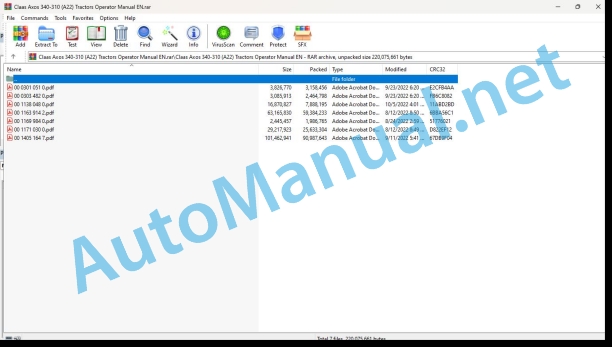
Claas Axos 340-310 (A22) Tractors Operator Manual EN
$50.00
- Model: Axos 340-310 (A22) Tractors
- Type Of Manual: Operator Manual
- Language: EN
- Format: PDF(s)
- Size: 183 MB
File List:
00 0301 051 0.pdf
00 0303 482 0.pdf
00 1138 048 0.pdf
00 1163 914 2.pdf
00 1169 984 0.pdf
00 1171 030 0.pdf
00 1405 164 7.pdf
00 0301 051 0.pdf:
PROFI CAM 3
Table of contents
1 Introduction
1.1 Notes on the manual
1.1.1 Validity of manual
1.1.2 Information about this Operator’s Manual
1.1.3 Symbols and notes
1.1.4 Optional equipment
1.1.5 Qualified specialist workshop
1.1.6 Maintenance information
1.1.7 Warranty notes
1.1.8 Spare parts and technical questions
1.2 Intended use
1.2.1 Intended use
1.2.2 Reasonably foreseeable misuse
2 Safety
2.1 Identifying warnings
2.1.1 Hazard signs
2.1.2 Signal word
2.2 Safety rules
2.2.1 Meaning of Operator’s Manual
2.2.2 Observing safety decals and warnings
2.2.3 Optional equipment and spare parts
3 Product description
3.1 Overview and method of operation
3.1.1 How the PROFI CAM works
3.2 Identification plates and identification number
3.2.1 Position of identification plates
3.2.2 Explanation of PROFI CAM identification plate
3.3 Information on the product
3.3.1 CE marking
4 Operating and control elements
4.1 Camera system
4.1.1 Camera system monitor
4.2 Menu structure
4.2.1 Main menu
4.2.2
4.2.3
4.2.4
4.2.5
4.2.6
5 Technical specifications
5.1 PROFI CAM
5.1.1 Monitor
5.1.2 Camera
5.1.3 Switch box
5.1.4 Degree of protection against foreign bodies and water
6 Preparing the product
6.1 Shutting down and securing the machine
6.1.1 Switching off and securing the machine
6.2 Prior to operation
6.2.1 Carry out prior to operation
6.2.2 Installing the sun protection
6.2.3 Aligning the camera
6.2.4 Connecting the camera electrics
7 Operation
7.1 Monitor
7.1.1 Switching on the monitor
7.1.2 Calling up the menu
7.1.3 Setting a menu item
7.1.4 Setting the image orientation
7.1.5 Setting automatic screen darkening
7.1.6 Image mirroring
7.1.7 Setting the trigger view
7.1.8 Setting the follow-up time for trigger view
7.1.9 Setting the display mode
7.1.10 Activating/deactivating a display mode
8 Faults and remedies
8.1 Electrical and electronic system
8.1.1 Overview of problems on PROFI CAM camera system
8.1.2 Replacing the switch box fuse
9 Maintenance
9.1 Maintenance intervals
9.1.1 Every 10 operating hours or daily
9.2 Camera system
9.2.1 Checking the camera system for dirt
9.2.2 Cleaning the camera
9.2.3 Cleaning the switch box
9.2.4 Cleaning the monitor
10 Placing out of operation and disposal
10.1 General Information
10.1.1 Putting out of operation and disposal
11 Technical terms and abbreviations
11.1 Abbreviations
11.1.1 Units
11.1.2 Abbreviations
11.1.3 Technical terms
00 0303 482 0.pdf:
PROFI CAM 4
Table of contents
1 Introduction
1.1 Notes on the manual
1.1.1 Validity of manual
1.1.2 Information about this Operator’s Manual
1.1.3 Symbols and notes
1.1.4 Optional equipment
1.1.5 Qualified specialist workshop
1.1.6 Maintenance information
1.1.7 Notes on warranty
1.1.8 Spare parts and technical questions
1.2 Intended use
1.2.1 Intended use
1.2.2 Reasonably foreseeable misuse
2 Safety
2.1 Identifying warnings
2.1.1 Hazard signs
2.1.2 Signal word
2.2 Safety rules
2.2.1 Meaning of Operator’s Manual
2.2.2 Structural changes
2.2.3 Optional equipment and spare parts
2.2.4 Operation only following proper putting into operation
2.2.5 Technical status
2.2.6 Respecting technical limit values
Respecting technical limit values
2.2.7 Hazards when driving on roads and fields
3 Product description
3.1 Overview and method of operation
3.1.1 How the PROFI CAM works
3.2 Identification plates and identification number
3.2.1 Identification plates
3.3 Information on the product
3.3.1 CE marking
4 Operating and display elements
4.1 Camera system
4.1.1 Camera system monitor
4.1.2 CEBIS
4.2 Menu structure
4.2.1 Main menu
4.2.2
4.2.3
4.2.4
4.2.5
4.2.6
5 Technical specifications
5.1 PROFI CAM
5.1.1 Monitor
5.1.2 Camera
5.1.3 Switch box
6 Preparing the product
6.1 Switching off and securing the machine
6.1.1 Switching off and securing the machine
6.2 Prior to putting into operation
6.2.1 Carry out prior to operation
6.2.2 Installing the sun protection
6.2.3 Aligning the camera
7 Operation
7.1 Monitor
7.1.1 Switching on the monitor
7.1.2 Calling up the menu
7.1.3 Setting a menu item
7.1.4 Setting the image orientation
7.1.5 Setting automatic screen darkening
7.1.6 Image mirroring
7.1.7 Setting the trigger view
7.1.8 Setting the follow-up time for trigger view
7.1.9 Setting the display mode
7.1.10 Activating/deactivating a display mode
8 Faults and remedies
8.1 Electric and electronic system
8.1.1 Overview of problems on PROFI CAM camera system
9 Maintenance
9.1 Maintenance intervals
9.1.1 Every 10 operating hours or daily
9.2 Camera system
9.2.1 Checking the camera system for dirt
9.2.2 Cleaning the camera
9.2.3 Cleaning the switch box
9.2.4 Cleaning the monitor
10 Putting out of operation and disposal
10.1 General information
10.1.1 Putting out of operation and disposal
11 Technical terms and abbreviations
11.1 Abbreviations
11.1.1 Units
11.1.2 Abbreviations
11.1.3 Technical terms
00 1138 048 0.pdf:
Technical support user guide
F0 General
This section concerns all the coded elements contained in chapter F. Each plate is first represented in 2D view with the list of relays and fuses. The plates are then represented schematically in one or several views.
F1 Function diagrams
Each diagram represents all devices, plates and their connections for a given use function, such as front lifting command or the fuel gauge (see below).
F2 Connector diagrams
This section lists all connectors, interconnections, and splices. Each element has a matching list of path and wire numbers (see below).
F3 Implantation diagrams
This section allows to know the precise location of each electric element on board the vehicle.
Contents
CLAAS COMPONENT NUMBERS (CCN) list 7
List of connectors 11
GENERAL WIRING 18
List of harnesses 19
List of grounding points 20
Fuse plates and electronic plates 21
CLAAS COMPONENT NUMBERS (CCN) list
List of connectors
GENERAL WIRING
List of harnesses
List of grounding points
Fuse plates and electronic plates
Primary services fuse plate V21
F1_001-060_TS_AXOS_CAB_0409_DIAGNOSTIC_GB.pdf
Contents
F1 – Function diagrams
Work lights
Front working lights on cab roof 7
Rear working lights on cab roof – (low roof) 8
Rear working lights on cab roof – (high roof) 9
Road signalling
Position and police plate lights 10
Dipped headlights 11
Main beam lights 12
Brake lights 13
Rotating beacon 14
Flashing indicators and hazard warning lights 16
Instrument panel lighting 17
Ventilation and A/C
Fan control 18
manual air conditioning 19
Rear lifting TCE 9 20
Front power take-off 21
Rear power take-off (Clutchless reverser) 22
Starting and loading circuit
Starting and loading circuit – (mechanical reverser) 24
Starting and loading circuit – (Clutchless reverser) 25
Pre-heating 26
Transmission
Forward – Reverse 27
4-wheel drive control 28
Hydraulic pressure and filter clogging 29
Transmission temperature – Shuttle reverser 30
Hydraulic shift Twinshift 31
Accessories
Cigarette lighter 32
Radio – Clock 33
Overhead light 34
Wiper/washer
Front wiper/washer with adjustable steering column 35
Front windscreen wiper/washer with fixed steering column 36
Rear screen wiper/washer 37
Networks
K and L lines 38
Controller Area Network (CAN) 39
Supply before contact 40
Supply after contact 41
Earth 42
Earth 43
Earth 44
Transmission module power supply TR1 45
Rear lifting module REH and control panel power supply V22 46
Diagnostic socket power supply 47
Dashboard module power supply DBD 48
Tractor/tool link
25A power socket – (cab) 49
Onboard computer and event counter 50
Charger socket 51
Brake system
Handbrake 52
Pneumatic seat 53
Transmission speed
Theoretical forward speed and transmission load 54
Fuel gauge 55
Oil pressure, air filter clogging, engine temperature 56
Fuel pump 57
Instrument panel
Calibration, dashboard display (Adjustable steering column) 58
Front working lights on cab roof
Rear working lights on cab roof – (low roof)
Rear working lights on cab roof – (high roof)
Position and police plate lights
Dipped headlights
Main beam lights
Brake lights
Rotating beacon
Flashing indicators and hazard warning lights
Instrument panel lighting
Fan control
manual air conditioning
Rear lifting TCE 9
Front power take-off
Rear power take-off (Clutchless reverser)
Rear power take-off (mechanical reverser)
Starting and loading circuit – (mechanical reverser)
Starting and loading circuit – (Clutchless reverser)
Pre-heating
Forward – Reverse
4-wheel drive control
Hydraulic pressure and filter clogging
Transmission temperature – Shuttle reverser
Hydraulic shift Twinshift
Cigarette lighter
Radio – Clock
Overhead light
Front wiper/washer with adjustable steering column
Front windscreen wiper/washer with fixed steering column
Rear screen wiper/washer
K and L lines
Controller Area Network (CAN)
Supply before contact
Supply after contact
Transmission module power supply TR1
Rear lifting module REH and control panel power supply V22
Diagnostic socket power supply
Dashboard module power supply DBD
25A power socket – (cab)
Onboard computer and event counter
Charger socket
Handbrake
Pneumatic seat
Theoretical forward speed and transmission load
Fuel gauge
Oil pressure, air filter clogging, engine temperature
Fuel pump
Calibration, dashboard display (Adjustable steering column)
Calibration, dashboard display (Fixed steering column)
F2_001-110_AXOS_CAB_0409_DIAGNOSTIC_GB.pdf
F2 Connector diagrams
Contents
J003 Connector -Cab bottom harness – Without air conditioning / V21 base plate
J004 Connector – Cab bottom harness – Without air conditioning / V21 base plate
J005 Connector – Cab bottom harness – manual air conditioning / V21 base plate
J005 Connector – Cab bottom harness – Without air conditioning / V21 base plate
J006 Connector – Front wiper/washer control
J007 Connector – Signaling control
J008 Connector – Cab bottom harness – manual air conditioning / V21 base plate
J008 Connector – Cab bottom harness – Without air conditioning / V21 base plate
J009 Connector – Clutchless reverser control
J010 Connector – Windscreen wipers
J011 Connector – Windscreen washers
J012 Connector – Ventilation motor
J013 Connector – Air conditioning thermostat
J014 Connector – Air conditioning control – recycling
J015 Connector – Cab inner supply harness / V21 base plate
J016 Connector – Cab inner supply harness / V21 base plate
J017 Connector – Front wiper motor
J018 Connector – Dashboard display selection
J019 Connector – Dashboard display selection
J020 Connector – Rotating beacon switch
J021 Connector – Hazard warning lights switch
J023 Connector – Trailer socket
J024 Connector – Seat
J025 Connector – RH police plate
J026 Connector – Cab bottom harness / V21 base plate
J029 Connector – Shunt base – Earths
J030 Connector – Rotating beacon indicator
J031 Connector – Warning lamps indicator
J032 Connector – Transmission computer
J034 Connector – Air conditioning compressor
J037 Connector – Cab ground
J038 Connector – Cab ground
J039 Connector – Grounding stud
J040 Connector – Shunt base – Earths – manual air conditioning
J040 Connector – Shunt base – Earths – Without air conditioning
J042 Connector – Front left indicator
J045 Connector – 4-wheel drive control
J046 Connector – Front power take-off control
J047 Connector – Diagnostic plug
J048 Connector – Reverser under torque transmission control harness / V21 base plate
J048 Connector – Transmission control harness – Mechanical reverser / V21 base plate
J048 Connector – ISC and REH transmission diagnostic connector / V21 base plate
J049 Connector – Control +/- ranges
J052 Connector – Reverser under torque transmission control harness / V21 base plate
J052 Connector – Transmission control harness – Mechanical reverser / V21 base plate
J052 Connector – ISC and REH transmission control harness / V21 base plate
J054 Connector – Engine speed sensor
J055 Connector – Forward drive solenoid valve
J056 Connector – Reverse solenoid valve
J057 Connector – PTO contact
J061 Connector – LH police plate
J062 Connector – clutchless reverser potentiometer
J063 Connector – BOC
J064 Connector – Control
J066 Connector – Reverser under torque transmission control harness / V21 base plate
J066 Connector – Mechanical reverser transmission control harness / V21 base plate
J066 Connector – ISC and REH transmission control harness / V21 base plate
J067 Connector – Charger indicator
J068 Connector – Equipotential base
J069 Connector – Reverser under torque ground base
J069 Connector – Mechanical reverser ground base
J069 Connector – ISC and REH transmission ground base
J070 Connector – Fuel level
J071 Connector – Pre-heat relay
J072 Connector – Front left external work light
J073 Connector – LH rotating beacon
J074 Connector – Rear left external work light
J075 Connector – Outside air temperature probe
J076 Connector – Left-hand loudspeaker
J077 Connector – Rear screen wiper/washer
J078 Connector – Right-hand loudspeaker
J079 Connector – Rear working light controls
J080 Connector – Overhead light
J081 Connector – Front work light control
J083 Connector – Front right external work light
J084 Connector – Rear right work light
J085 Connector – Handbrake
J087 Connector – Grounding stud
J088 Connector – Dimmed light selection switch and indicator
J089 Connector – Dimmed light selection switch and indicator
J090 Connector – Front right signaling light
J091A Connector – Cigarette lighter
J095 Connector – Left stop contact
J096 Connector – Right stop contact
J097 Connector – Loader
J098 Connector – Rear PTO controls
J099 Connector – Rear PTO controls
J100 Connector – Fan control
J101 Connector – Preheating fuse
J105 Connector – Lift calculator
J106 Connector – Electrohydraulic lifting control panel
J111 Connector – LH dipped light
J112 Connector – Starter
J113 Connector – Terminal + – Battery
J114 Connector – Earth
J115 Connector – Implement electrical socket
J116 Connector – Electric stop
J117 Connector – Diesel pump
J118 Connector – Key operated ignition
J119 Connector – Engine water temp. earth
J121 Connector – Pre-heating
J123 Connector – Air filter blocked
J124 Connector – Air filter blocked
J125 Connector – Pressure switch
J126 Connector – Pressure switch
J127 Connector – D+ alternator – Alternator charge
J128 Connector – W alternator – Engine speed
J129 Connector – Terminal + – Battery
J130 Connector – Alternator ground
J132 Connector – Alternator ground
J133 Connector – Alternator ground
J134 Connector – Pre-heat relay
J135 Connector – Pre-heat relay
J136 Connector – Pre-heat relay
J137 Connector – Battery
J143 Connector – Hydraulic pressure
J144 Connector – Hydraulic pressure
J145 Connector – Power take-off clutch
J146 Connector – Power take-off clutch
J147 Connector – Front windscreen washer pump
J148 Connector – Rear windscreen washer pump
J150 Connector – Gearbox contact
J151 Connector – Gearbox contact
J152 Connector – Lift valve
J153 Connector – Lowering valve
J154 Connector – Position sensor
J155 Connector – Load sensor
J156 Connector – Transmission oil temp. sensor
J157 Connector – LH headlight
J158 Connector – LH headlight
J159 Connector – LH dipped light
J160 Connector – LH dipped light
J161 Connector – RH headlight
J162 Connector – RH headlight
J163 Connector – Horn
J164 Connector – Horn
J165 Connector – RH dipped light
J166 Connector – RH dipped light
J170D Connector – Rear signaling lights
J170G Connector – Rear signaling lights
J171 Connector – Front right inside work light
J172 Connector – Front left inside work light
J173 Connector – Radio earth
J174D Connector – Raise electrohydraulic lifting control
J174G Connector – Raise electrohydraulic lifting control
J175D Connector – Lower electrohydraulic lifting control
J175G Connector – Lower electrohydraulic lifting control
J176 Connector – Preheating fuse
J180 Connector – Rear left inside work light
J181 Connector – Rear right inside work light
J184 Connector – Fan control – (Manual air conditioning)
J184 Connector – Fan control – (without air conditioning)
J185 Connector – Fan control
J186 Connector – Fan control
J189 Connector -Implement electrical socket
J194 Connector – RH dipped light
J199 Connector – Radio
J200 Connector – Radio
J202 Connector – Cab top harness – High roof / Onboard computer option harness
J203 Connector – Battery
J204 Connector – Battery
J205 Connector – 4-wheel drive solenoid valve
J206 Connector – 2PS solenoid valve
J207 Connector – Shuttle reverser speed sensor
J208 Connector – Power take-off solenoid valve
J220 Connector – CAN +R
J220 Connector – CAN +R – Mechanical reverser transmission
J229 Connector – Connector
J253 Connector – Connector
J300 Connector – Battery breaker input lug
J300 Connector – Battery breaker input lug
J301 Connector – Connector
J313 Connector – Battery master switch
J314 Connector – Battery breaker output lug
J324 Connector – Key operated ignition
J325 Connector – Left stop contact
J326 Connector – Right stop contact
J327 Connector – Instrument panel
J328 Connector – Mechanical reverser dashboard
J328 Connector – Instrument panel – Shuttle reverser
J329 Connector – Instrument panel
J330 Connector – CAN + R
J338 Connector – Implement electrical socket
J339 Connector – Implement electrical socket
J340 Connector – Implement electrical socket
J341 Connector – Implement electrical socket
J342 Connector – Oil pressure
J343 Connector – Grounding stud
Splice N001
Splice N002
Splice N003
Splice N004
Splice N005
Splice N006
Splice N007 – Mechanical reverser
Splice N007 – Shuttle reverser
Splice N008
Splice N009
Splice N010
Splice N011
Splice N012
Splice N013
Splice N014
Splice N015
Splice N018
Splice N019
Splice N020
P002 – J002 Connector – Interconnection
P006 – J006 Connector – Interconnection
P028 – J028 Connector – Interconnection – Low roof
P028 – J028 Connector – Interconnection – High roof
P041 – J041 Connector – Interconnection
P050 – J050 Connector – Interconnection – Reverser under torque and electrohydraulic lifting
P050 – J050 Connector – Interconnection – Shuttle reverser
P050 – J050 Connector – Interconnection – Mechanical reverser
P053 – J053 Connector – Interconnection – Left-hand fender
P053 – J053 Connector – Interconnection – Electro-hydraulic lift – Left-hand fender
P065 – J065 Connector – Interconnection – Right-hand fender
P065 – J065 Connector – Interconnection – Electro-hydraulic lift – Right-hand fender
P091 – J091 Connector – Interconnection
P122 – J122 Connector – Interconnection
P189 – J189 Connector – Interconnection
P295 – J295 Connector – Interconnection – Shuttle reverser
P295 – J295 Connector – Interconnection – Mechanical reverser
P296 – J296 Connector – Interconnection – Mechanical reverser and manual A/C
P296 – J296 Connector – Interconnection – Reverser under torque and manual A/C
P296 – J296 Connector – Interconnection – Mechanical reverser without A/C
P296 – J296 Connector – Interconnection – Reverser under torque without A/C
P297 – J297 Connector – Interconnection – Mechanical reverser
P297 – J297 Connector – Interconnection – Shuttle reverser
P298 – J298 Connector – Interconnection
P298 – J298 Connector – Interconnection – Mechanical reverser
P299 – J299 Connector – Interconnection
P344 – J344 Connector – Interconnection
F3_001-030_AXOS_CAB_0409_DIAGNOSTIC_GB.pdf
Contents
F3 – Implantation diagrams
01 – Cab bottom harness 5
02 – Instrument panel harness – Mechanical reverser – With air conditioning 6
02 – Instrument panel harness – Mechanical reverser – Without air conditioning 7
02 – Instrument panel harness – reverser under torque – With air conditioning 8
02 – Instrument panel harness – reverser under torque – Without air conditioning 9
03 – Fender harness 10
03 – Fender harness – Electro-hydraulic lift 11
04 – Low roof tob cab harness 12
04 – High roof top cab harness 13
07 – Cab supply harness 14
09 – Transmission harness – Mechanical reverser 15
09 – Transmission harness – Shuttle reverser 16
09 – Transmission harness – Shuttle reverser – Electro-hydraulic lift 17
10 – Engine harness – 4 cylinders 18
11 – Radiator cowling harness 19
13 – Transmission control harness – Mechanical reverser 20
13 – Transmission control harness – Shuttle reverser 21
13 – Transmission control harness – Shuttle reverser – Electro-hydraulic lift 22
27 – Cab inner supply harness 23
49 – Cab tools power outlet harness 24
52 – Cigarette lighter harness 25
66 – Harness – Wiper/washer – Instrument panel display 26
C2 – Short-circuit cable 27
C3 – Positive launch cable 28
C4 – Positive launch cable 29
C6 – Negative launch cable 30
01 – Cab bottom harness
02 – Instrument panel harness – Mechanical reverser – With air conditioning
02 – Instrument panel harness – Mechanical reverser – Without air conditioning
02 – Instrument panel harness – reverser under torque – With air conditioning
02 – Instrument panel harness – reverser under torque – Without air conditioning
03 – Fender harness
03 – Fender harness – Electro-hydraulic lift
04 – Low roof tob cab harness
04 – High roof top cab harness
07 – Cab supply harness
09 – Transmission harness – Mechanical reverser
09 – Transmission harness – Shuttle reverser
09 – Transmission harness – Shuttle reverser – Electro-hydraulic lift
10 – Engine harness – 4 cylinders
11 – Radiator cowling harness
13 – Transmission control harness – Mechanical reverser
13 – Transmission control harness – Shuttle reverser
13 – Transmission control harness – Shuttle reverser – Electro-hydraulic lift
27 – Cab inner supply harness
49 – Cab tools power outlet harness
52 – Cigarette lighter harness
66 – Harness – Wiper/washer – Instrument panel display
C2 – Short-circuit cable
C3 – Positive launch cable
C4 – Positive launch cable
C6 – Negative launch cable
00 1163 914 2.pdf:
AXOS 340
Table of contents
1 Introduction
1.1 Notes on the manual
1.1.1 Using the operator’s manual
Important information concerning this operator’s manual
Structure based on tractor sub-assemblies
Search and find
Direction indications
Specific terminology
Optional and additional equipment
1.1.2 Symbols and instructions
Text and illustrations
Highlighting dangers and warnings
1.1.3 Validity of the operator’s manual
1.1.4 Transferring the tractor to a third party
1.1.5 Technical information
2 Safety
2.1 Safety rules
2.1.1 Appropriate use
2.1.2 Inappropriate use
2.1.3 European regulation
2.1.4 Safety and accident prevention instructions
2.1.5 Driving the tractor
2.1.6 Checking the condition of the tractor
2.1.7 Climbing into the cab and out of the tractor
Climbing into the tractor
Climbing out of the tractor
2.1.8 Precautions to be taken before starting up
2.1.9 Cab
Safety structure of the cab
Polluted environment
2.1.10 Hitching implements
2.1.11 Adjustments and maintenance work
Special notes on mounting the tractor on axle stands
2.1.12 Using the front and rear power take-off
2.1.13 Fuel
2.1.14 Engine coolant
2.1.15 Air conditioning
2.1.16 Electrical system
2.1.17 Specific recommendations for this tractor
2.1.18 Forest applications
2.1.19 Stationary working
2.1.20 Twin wheels
2.2 Safety decals on the tractor
2.2.1 General advice regarding the safety markings
2.2.2 Warning symbols
3 Tractor description
3.1 Overview
3.1.1 Front left-hand view
3.1.2 Rear right 3/4 view
3.2 Identification plates and vehicle identification number
3.2.1 Tractor identification plate
Tractor identification number
Tractor regulation type
Tractor serial number
3.2.2 Additional cab identification plate
3.2.3 Tractor power label
3.2.4 Engine identification plate
3.2.5 Cab identification plate
4 Operating and display elements
4.1 Cab and operator’s platform
4.1.1 Driving position
4.1.2 Dashboard
4.1.3 TCE 9 electrohydraulic rear linkage controls
4.1.4 Instrument panel
4.1.5 Transmission display
4.1.6 Manual air conditioning
4.1.7 Driving position controls
Indicator lights and horn
Warning beacon and hazard warning lights
Front windscreen washer and wiper
4.1.8 Cab top controls
Work lights
Rear screen wiper and washer
4.1.9 Switch box electrical socket
4.1.10 Hydraulic controls
4.2 Electric and electronic system
4.2.1 External controls (TCE9 electrohydraulic rear linkage)
5 Technical specifications
5.1 AXOS 340
5.1.1 Dimensions
5.1.2 Weight
5.1.3 Engine
5.1.4 Gearbox
5.1.5 Travel speeds
5.1.6 Rear axle
5.1.7 Table of rear tracks
5.1.8 Tyre combinations
5.1.9 Tyre load capacity and inflation pressure
Front tyre
Rear tyres
5.1.10 Brakes
5.1.11 Direction
5.1.12 Rear linkage
5.1.13 Rear power take-off
5.1.14 Hydraulic circuits
5.1.15 Hydraulic control valve combinations
5.1.16 Electrical circuit
5.1.17 Cab specifications
Sound level heard by the driver (according to European Directive 2009/76)
Sound level heard by a passer-by (according to European Directive 2009/63 Annex VI)
5.1.18 Seat vibration level
5.1.19 Load capacities
5.1.20 Maximum authorised tow weights
5.1.21 Ballast
5.1.22 Lubricants/Hydraulic oil
5.1.23 Engine coolant
5.1.24 Air conditioning refrigerant
6 Tractor preparation
6.1 Engine
6.1.1 Fuel
Quality requirement
Special notes on biofuels
Handling fuel
6.1.2 Topping up the fuel
6.2 Frame
6.2.1 Adjusting the rear axle track
6.2.2 General information about the tyres
6.2.3 Inflation pressure
Effect on soil compaction
Effect on consumption
6.2.4 Specifications
Load index
Speed symbol
6.3 Brake
6.3.1 Coupling the brake pedals
6.4 Steering
6.4.1 Steering column
6.5 Rear power lift
6.5.1 Axle stands
6.5.2 Top link
6.5.3 Stabilisers
6.5.4 External controls
With TCE9 electrohydraulic rear linkage
With mechanically controlled rear linkage
6.6 Rear power take-off
6.6.1 Replacing the rear power take-off fitting
Removing the rear power take-off fitting
Refitting the rear power take-off fitting
6.7 Rear hydraulic system
6.7.1 Rear pressure taps
Connecting/Disconnecting the pressure connectors
Free return to hydraulic tank
6.7.2 Single/double action setting
6.7.3 Motorized flow controller
6.8 Electric and electronic system
6.8.1 Electrical sockets
Switch box electrical socket
External electrical socket
6.8.2 Adjust the dipped beam headlights
Adjusting the engine bonnet dipped beam headlights
Adjusting the cab dipped beam headlights
6.9 Cab and operator’s platform
6.9.1 Adjusting the driver’s comfort seat
6.9.2 Installing a control box in the cab
6.9.3 Routing the cables of a control box
6.9.4 Storage
6.10 Assembly parts and machine body
6.10.1 Engine bonnet
Opening the engine bonnet
Closing the engine bonnet
6.10.2 Ballast
6.10.3 Ballast water
6.10.4 Balancing the tractor with mounted implements
Summary table
6.10.5 Installing additional equipment
6.10.6 Tool box
6.11 Transport of the tractor
6.11.1 Transporting the tractor
6.11.2 Loading the tractor
7 Operation
7.1 Engine
7.1.1 Running in
7.1.2 Starting the engine
Preliminary operations
Start up
7.1.3 Accelerator pedal
7.1.4 Hand accelerator
7.1.5 Engine stops
7.2 Transmission, clutch and driveshaft
7.2.1 Selecting the tractor’s direction of travel
7.2.2 Clutch pedal
7.2.3 Gear selection
7.2.4 Gear range selection
7.2.5 Differential lock
7.3 Brake
7.3.1 Service brakes
7.3.2 Parking brake (auxiliary and parking brake)
7.4 Mechanical rear linkage
7.4.1 Position control
7.4.2 Draft control
7.4.3 Mixed control
7.5 Electronic rear linkage
7.5.1 Recommendations
7.5.2 Road transport safety
7.5.3 Unlocking the rear linkage
7.5.4 Selecting modes
7.5.5 Checking the rear linkage position
7.5.6 Checking the rear linkage force
7.5.7 Rear linkage external controls
7.5.8 Rear linkage upper stop
7.5.9 Rear linkage lower link lowering speed
7.5.10 Rear linkage transport damper
7.6 Rear power take-off
7.6.1 Power take-off speed selection
7.6.2 Rear power take-off engagement
Procedure for setting off again
7.6.3 Stationary working
7.7 Rear hydraulic system
7.7.1 Association between the controls and the rear pressure taps
7.7.2 Using the auxiliary hydraulic control valve linear controls
7.7.3 Stationary working
7.8 Electric and electronic system
7.8.1 Manual circuit breaker
7.9 Cab and operator’s platform
7.9.1 Instrument panel display
Setting the time on the clock
7.9.2 Heating – Ventilation – Manual air conditioning
Adjusting the ventilaair flow rate
Adjusting the ventilated air temperature
Managing the ventilation direction
Activating the air conditioning function
Activating the air recirculation function
7.9.3 Overhead light
8 Faults and remedies
8.1 Alarms
8.1.1 Primary alarms
8.1.2 Secondary alarms
8.1.3 Other alarms
8.2 Engine
8.2.1 Faults caused by a low fuel level
8.2.2 Starting assistance
Assisted starting by towing
Assisted starting using an external battery
8.3 Frame
8.3.1 Fitting a jack
8.3.2 Replacing a wheel
Rear wheels
Front wheel
8.3.3 Towing the tractor
Towing with the engine stopped
Towing with the engine running
8.4 Electric and electronic system
John Deere Repair Technical Manual PDF
John Deere Parts Catalog PDF
John Deere Harvesters 8500 and 8700 Parts Catalog CPCQ24910 Spanish
John Deere Repair Technical Manual PDF
John Deere Repair Technical Manual PDF
John Deere Repair Technical Manual PDF
John Deere Application List Component Technical Manual CTM106819 24AUG20
John Deere Repair Technical Manual PDF
John Deere 18-Speed PST Repair Manual Component Technical Manual CTM168 10DEC07
John Deere Repair Technical Manual PDF
John Deere Repair Technical Manual PDF
John Deere Transmission Control Unit Component Technical Manual CTM157 15JUL05
John Deere Repair Technical Manual PDF

