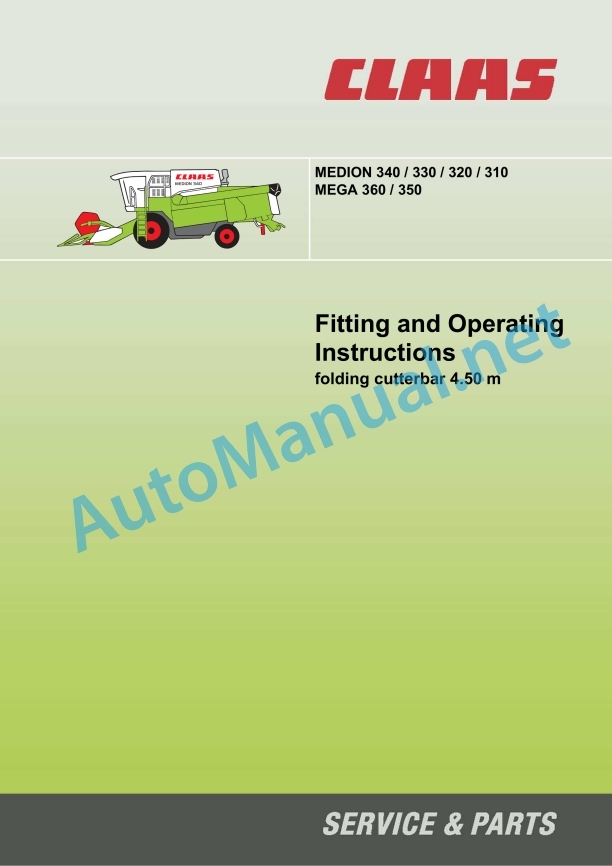
Claas C450 Folding Do Mega Medion (431) Combines Operator Manual EN
$50.00
- Model: C450 Folding Do Mega Medion (431) Combines
- Type Of Manual: Operator Manual
- Language: EN
- Format: PDF(s)
- Size: 8.8 MB
File List:
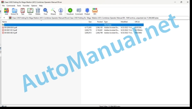
00 0299 838 0.pdf
00 0301 051 0.pdf
00 0303 482 0.pdf
00 0299 838 0.pdf:
Introduction
Introduction
Table of contents
Table of contents
Attention!
Special note
Type plate / serial number
Safety rules
Safety rules
Identification of warning and danger signs
Correct use of the vehicle
General safety and accident prevention regulations
Safety Locks
Cylinder safety lock
Reel supports
Insert the reel supports
Remove the reel supports and store them away
Safety decals with pictorials
Specifications
Weights / Dimensions / Safety devices
Weights / Dimensions
Safety feature:
Setting the slipping clutch
Prior to operation
Carry out prior to initial operation
Driving lights for road use
Driving lights for road use
Switching over the driving lights
Cutterbar cylinder
Ancillary equipment
Additional weights
MEDION 340 – 310 / MEGA 360 / 350
Liquid filler for the steering axle wheels
Fitting the cover weights
Scope of components – Cover weights
Scope of components – steering axle weights
Steering axle weights
Fitting the steering axle weights (Additional equipment)
Fitting and Operation
Fitting additional equipment
Fitting stops in the feeder housing
Scope of parts – Fitting
Fitting the stops
Lock the cutterbar at the sides
Modifying the cutterbar Auto-Contour for machines without Auto-Contour
Fitting the switching device and the driving lights
Shortening the flat key MEGA 360 / MEDION 340
Setting the additional headlights
Fitting the cutterbar
Tilting the cutterbar from the transport position
Fitting and removing the cutterbar.
Fitting the cutterbar – folded – (Cutterbar in the transport position)
Aligning the cutterbar (Cutterbar without Auto-Contour)
Connecting the hydraulic hoses
Connecting the plug
Changing the cutterbar from transport position to operating position
Changing the cutterbar from operating position to transport position
Removing the cutterbar – folded in –
Fitting the cutterbar – unfolded – (Cutterbar in operating position)
Connecting the universal drive shafts
Connecting the hydraulic hoses
Connecting the plug
Removing the cutterbar – unfolded – (Cutterbar in operating position)
Adjustments to the cutterbar
Crop dividers
Crop lifters
Reel speed
Intake auger
Cutterbar skids
Malfunction
Cause or Remedy
Maintenance
Transmissions
Knife drive casing
Oil filling:
(Fig. 1, 2)
(Fig. 2)
Check the oil level:
Angle drive for the reel drive
Knife drive
Drive chain tensioning
Cleaning the guide rail of the locking cylinder
Adjusting the double fingers
Lubrication chart
Lubricants and notes
00 0301 051 0.pdf:
PROFI CAM 3
Table of contents
1 Introduction
1.1 Notes on the manual
1.1.1 Validity of manual
1.1.2 Information about this Operator’s Manual
1.1.3 Symbols and notes
1.1.4 Optional equipment
1.1.5 Qualified specialist workshop
1.1.6 Maintenance information
1.1.7 Warranty notes
1.1.8 Spare parts and technical questions
1.2 Intended use
1.2.1 Intended use
1.2.2 Reasonably foreseeable misuse
2 Safety
2.1 Identifying warnings
2.1.1 Hazard signs
2.1.2 Signal word
2.2 Safety rules
2.2.1 Meaning of Operator’s Manual
2.2.2 Observing safety decals and warnings
2.2.3 Optional equipment and spare parts
3 Product description
3.1 Overview and method of operation
3.1.1 How the PROFI CAM works
3.2 Identification plates and identification number
3.2.1 Position of identification plates
3.2.2 Explanation of PROFI CAM identification plate
3.3 Information on the product
3.3.1 CE marking
4 Operating and control elements
4.1 Camera system
4.1.1 Camera system monitor
4.2 Menu structure
4.2.1 Main menu
4.2.2
4.2.3
4.2.4
4.2.5
4.2.6
5 Technical specifications
5.1 PROFI CAM
5.1.1 Monitor
5.1.2 Camera
5.1.3 Switch box
5.1.4 Degree of protection against foreign bodies and water
6 Preparing the product
6.1 Shutting down and securing the machine
6.1.1 Switching off and securing the machine
6.2 Prior to operation
6.2.1 Carry out prior to operation
6.2.2 Installing the sun protection
6.2.3 Aligning the camera
6.2.4 Connecting the camera electrics
7 Operation
7.1 Monitor
7.1.1 Switching on the monitor
7.1.2 Calling up the menu
7.1.3 Setting a menu item
7.1.4 Setting the image orientation
7.1.5 Setting automatic screen darkening
7.1.6 Image mirroring
7.1.7 Setting the trigger view
7.1.8 Setting the follow-up time for trigger view
7.1.9 Setting the display mode
7.1.10 Activating/deactivating a display mode
8 Faults and remedies
8.1 Electrical and electronic system
8.1.1 Overview of problems on PROFI CAM camera system
8.1.2 Replacing the switch box fuse
9 Maintenance
9.1 Maintenance intervals
9.1.1 Every 10 operating hours or daily
9.2 Camera system
9.2.1 Checking the camera system for dirt
9.2.2 Cleaning the camera
9.2.3 Cleaning the switch box
9.2.4 Cleaning the monitor
10 Placing out of operation and disposal
10.1 General Information
10.1.1 Putting out of operation and disposal
11 Technical terms and abbreviations
11.1 Abbreviations
11.1.1 Units
11.1.2 Abbreviations
11.1.3 Technical terms
00 0303 482 0.pdf:
PROFI CAM 4
Table of contents
1 Introduction
1.1 Notes on the manual
1.1.1 Validity of manual
1.1.2 Information about this Operator’s Manual
1.1.3 Symbols and notes
1.1.4 Optional equipment
1.1.5 Qualified specialist workshop
1.1.6 Maintenance information
1.1.7 Notes on warranty
1.1.8 Spare parts and technical questions
1.2 Intended use
1.2.1 Intended use
1.2.2 Reasonably foreseeable misuse
2 Safety
2.1 Identifying warnings
2.1.1 Hazard signs
2.1.2 Signal word
2.2 Safety rules
2.2.1 Meaning of Operator’s Manual
2.2.2 Structural changes
2.2.3 Optional equipment and spare parts
2.2.4 Operation only following proper putting into operation
2.2.5 Technical status
2.2.6 Respecting technical limit values
Respecting technical limit values
2.2.7 Hazards when driving on roads and fields
3 Product description
3.1 Overview and method of operation
3.1.1 How the PROFI CAM works
3.2 Identification plates and identification number
3.2.1 Identification plates
3.3 Information on the product
3.3.1 CE marking
4 Operating and display elements
4.1 Camera system
4.1.1 Camera system monitor
4.1.2 CEBIS
4.2 Menu structure
4.2.1 Main menu
4.2.2
4.2.3
4.2.4
4.2.5
4.2.6
5 Technical specifications
5.1 PROFI CAM
5.1.1 Monitor
5.1.2 Camera
5.1.3 Switch box
6 Preparing the product
6.1 Switching off and securing the machine
6.1.1 Switching off and securing the machine
6.2 Prior to putting into operation
6.2.1 Carry out prior to operation
6.2.2 Installing the sun protection
6.2.3 Aligning the camera
7 Operation
7.1 Monitor
7.1.1 Switching on the monitor
7.1.2 Calling up the menu
7.1.3 Setting a menu item
7.1.4 Setting the image orientation
7.1.5 Setting automatic screen darkening
7.1.6 Image mirroring
7.1.7 Setting the trigger view
7.1.8 Setting the follow-up time for trigger view
7.1.9 Setting the display mode
7.1.10 Activating/deactivating a display mode
8 Faults and remedies
8.1 Electric and electronic system
8.1.1 Overview of problems on PROFI CAM camera system
9 Maintenance
9.1 Maintenance intervals
9.1.1 Every 10 operating hours or daily
9.2 Camera system
9.2.1 Checking the camera system for dirt
9.2.2 Cleaning the camera
9.2.3 Cleaning the switch box
9.2.4 Cleaning the monitor
10 Putting out of operation and disposal
10.1 General information
10.1.1 Putting out of operation and disposal
11 Technical terms and abbreviations
11.1 Abbreviations
11.1.1 Units
11.1.2 Abbreviations
11.1.3 Technical terms
John Deere Repair Technical Manual PDF
John Deere Repair Technical Manual PDF
John Deere Repair Technical Manual PDF
John Deere Application List Component Technical Manual CTM106819 24AUG20
John Deere Repair Technical Manual PDF
John Deere Parts Catalog PDF
John Deere Tractors 7500 Parts Catalog CPCQ26568 30 Jan 02 Portuguese
John Deere Repair Technical Manual PDF
John Deere PowerTech M 10.5 L and 12.5 L Diesel Engines COMPONENT TECHNICAL MANUAL CTM100 10MAY11
John Deere Repair Technical Manual PDF
John Deere 16, 18, 20 and 24HP Onan Engines Component Technical Manual CTM2 (19APR90)
John Deere Repair Technical Manual PDF
John Deere Diesel Engines POWERTECH 2.9 L Component Technical Manual CTM126 Spanish
John Deere Repair Technical Manual PDF


