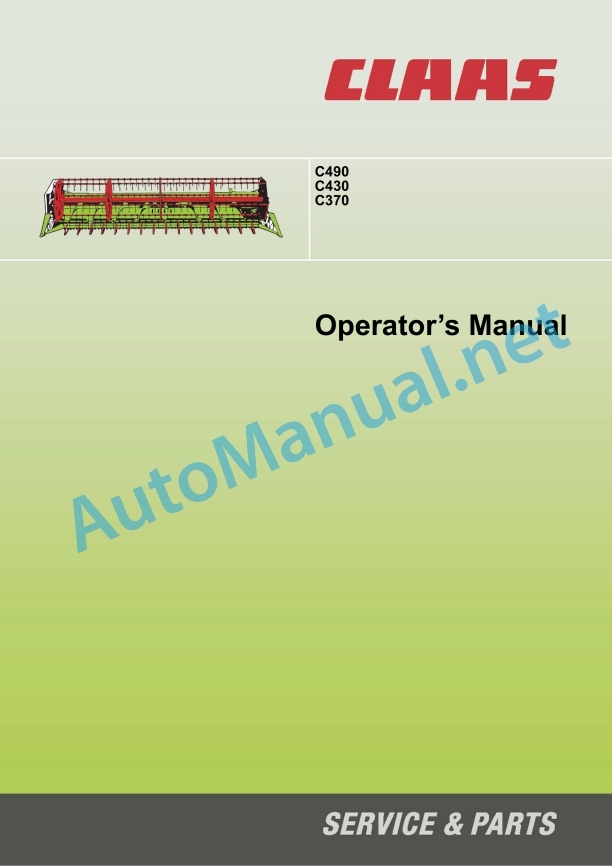
Claas C490-C300 Lexion Tucano (527) Combines Operator Manual EN
$50.00
- Model: C490-C300 Lexion Tucano (527) Combines
- Type Of Manual: Operator Manual
- Language: EN
- Format: PDF(s)
- Size: 24.0 MB
File List:
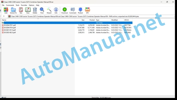
00 0294 979 1.pdf
00 0294 979 4.pdf
00 0301 051 0.pdf
00 0303 482 0.pdf
00 0294 979 1.pdf:
Contents
1 Introduction
1.1 General Information
1.1.1 How to use this manual
1.1.2 Validity of instructions
1.1.3 Specifications
1.2 Identification plates and identification numbers
1.2.1 Spare parts and technical questions
1.2.2 Identification plate
2 Safety precautions
2.1 General Information
2.1.1 Important information
2.1.2 General safety and accident prevention regulations
2.1.3 Intended use
2.1.4 Reasonable foreseeable misuse
2.1.5 Precautionary measures
2.2 General safety measures
2.2.1 Applying the feeder housing safety lock
2.2.2 Disengaging feed rake conveyor safety lock
2.2.3 Engaging the reel safety lock
2.2.4 Disengaging reel safety lock
2.2.5 Attaching finger bar safety bar
2.2.6 Compressed air and water
2.2.7 Danger of injury due to escaping hydraulic liquid
2.2.8 Burn prevention
2.2.9 Oils
2.2.10 Fire prevention and explosion prevention
2.2.11 Lines, Tubes and Hoses
2.2.12 Before every start-up
2.2.13 Putting the machine into operation
2.2.14 Road travel
2.2.15 Parking
2.2.16 First aid measures
2.2.17 Decommissioning and disposal
2.3 Safety rules
2.3.1 Identification of warning and danger signs
2.4 Safety decals
2.4.1 General information on safety decals
2.4.2 Power output / Drives
2.4.3 Crop feeding
2.4.4 Various components / Machine body
3 Specifications
3.1 C490 / C430 / C370 – TYPE 527
3.1.1 Dimensions
3.1.2 Weights
3.1.3 Crop feeding
3.1.4 Feeder unit
3.1.5 Mowing unit
3.1.6 Safety features
4 Prior to initial operation
4.1 General Information
4.1.1 General warnings
4.1.2 Initial operation check list
4.2 Crop feeding
4.2.1 Remove the transport safety equipment for the reel
5 Prior to each operation
5.1 General Information
5.1.1 General warnings
5.1.2 Checklist for putting the machine into operation
5.2 Feeder unit
5.2.1 Checking the adjustment of stripper profiles
6 Mounting/removing front attachment
6.1 General Information
6.1.1 General warnings
6.2 General assembly and settings
6.2.1 Mounting the front attachment
6.2.2 Dismounting the front attachment
6.3 Power output / drives
6.3.1 Installing universal drive shaft
6.3.2 Removing universal drive shaft
6.4 Hydraulic system
6.4.1 Mounting the multi-coupler
6.4.2 Dismounting the multi-coupler
6.5 Various components / Machine body
6.5.1 Suspending front attachment
6.5.2 Interlocking the front attachment
6.5.3 Unlocking the front attachment
6.5.4 Unhitching front attachment
7 Fieldwork settings
7.1 General Information
7.1.1 General warnings
7.2 Mowing unit
7.2.1 Installing the crop lifters (optional equipment)
7.2.2 Removing the crop lifters (optional equipment)
7.2.3 Adjusting the skids
8 Fieldwork
8.1 General Information
8.1.1 General warnings
8.2 General operation
8.2.1 Before working in the field
8.2.2 Checking the crop intake
8.3 Crop feeding
8.3.1 Adjusting the reel tines
8.3.2 Adjusting the crop dividers
8.4 Feeder unit
8.4.1 Adjusting the stripper profile
8.4.2 Adjusting the position of the intake auger
8.4.3 Adjusting the intake auger fingers
8.4.4 Auger baffle plate extension
8.4.5 Installing the baffle plate extension
8.4.6 Removing the auger baffle plate extension
8.4.7 Adjusting the intake auger speed
9 Faults and remedies
9.1 General Information
9.1.1 General warnings
9.2 General problems and remedies
9.2.1 Crop is not picked up
9.2.2 Cutterbar is not level
9.2.3 Flow of material from the cutterbar is uneven
9.2.4 Poor crop feeding or wrapping
9.2.5 Auger stops
9.2.6 Cutting height
9.2.7 Knife problems
9.2.8 Knife is stopping
9.2.9 Material is wrapping around the reel
9.2.10 Reel fingers are touching the finger bar
9.2.11 Reel is not level
9.2.12 Reel stops
9.2.13 Reel does not rotate
9.2.14 Foreign material on the tip of the crop divider
9.3 Hydraulic system
9.3.1 Bleeding reel cylinders
9.4 Crop feeding
9.4.1 Adjusting the reel height
9.4.2 Adjusting the reel speed sensor
10 Maintenance
10.1 General Information
10.1.1 General warnings
10.2 General maintenance notes
10.2.1 Fixing material
10.2.2 Maintenance operations after the harvest
10.2.3 Tightening torques for metric standard threads
10.2.4 Tightening torques for metric fine threads
10.2.5 Tightening torques for hydraulic screw fittings with ferrule according to DIN 3861
10.2.6 Tightening torques for hydraulic screw fittings and air conditioner fittings with a sealing cone and O-ring DIN 3865
10.2.7 Tightening torques for bolt fittings in plastic parts
10.3 Maintenance schedule
10.3.1 Service intervals
10.4 Lubricants chart
10.4.1 Lubricants
10.5 Gearbox / Clutch
10.5.1 Checking the knife drive gearbox oil level
10.5.2 Topping up knife drive gearbox oil
10.5.3 Draining knife drive gearbox oil
10.6 Power output / drives
10.6.1 Removing the knife drive belt
10.6.2 Installing the knife drive belt
10.6.3 Adjusting the knife drive belt
10.6.4 Tensioning intake auger drive chain
10.6.5 Tensioning reel drive chain
10.6.6 Checking chain tension
10.7 Mowing unit
10.7.1 Changing the knives
10.7.2 Adjusting knife clips
11 Lubrication chart
11.1 General Information
11.1.1 General warnings
11.2 Lubrication points
11.2.1 Lubrication intervals
11.2.2 Lubrication points – 10 h on the left
11.2.3 Lubrication points – 100 h on the left
11.2.4 Lubrication points – 100 h on the right
11.2.5 Lubrication points – 250 h on the left
11.2.6 Lubrication points – 500 h on the left
00 0294 979 4.pdf:
C 490C 430C 370
Table of contents
1 Introduction
1.1 General information
1.1.1 Validity of manual
1.1.2 Information about this Operator’s Manual
1.1.3 Symbols and notes
1.1.4 Optional equipment
1.1.5 Qualified specialist workshop
1.1.6 Maintenance notes
1.1.7 Warranty notes
1.1.8 Spare parts and technical questions
1.2 Intended use
1.2.1 Intended use
1.2.2 Reasonably foreseeable misuse
2 Safety
2.1 Identifying warnings
2.1.1 Hazard signs
2.1.2 Signal word
2.2 Safety rules
2.2.1 Importance of Operator’s Manual
2.2.2 Observing safety decals and warnings
2.2.3 Requirements for all persons working with the machine
2.2.4 Hazard areas
2.2.5 Standing between machine and front attachment
2.2.6 Fitting the front attachment to the machine
2.2.7 Danger of injury from rotating shafts
2.2.8 Structural changes
2.2.9 Optional equipment and spare parts
2.2.10 Operation only following proper putting into operation
2.2.11 Technical condition
2.2.12 Danger resulting from damage to the machine
2.2.13 Keeping the safety devices functional
2.2.14 Personal protective equipment
2.2.15 Wearing suitable clothing
2.2.16 Removing dirt and loose objects
2.2.17 Preparing the machine for road travel
2.2.18 Unsuitable operating materials
2.2.19 Safe handling of operating materials and auxiliary materials
2.2.20 Environmental protection and disposal
2.2.21 Electrocution by electrical system
2.2.22 Pressurised fluids
2.2.23 Only carry out work on the machine when it is stopped
2.2.24 Maintenance operations and repair work
2.2.25 Raised machine parts and loads
2.2.26 Hazard from welding work
2.3 Safety marking
2.3.1 Layout of safety decals
2.3.2 Safety decals on the front attachment
2.4 Safety devices
2.4.1 Applying the reel safety locks
2.4.2 Unlocking the reel safety locks
2.4.3 Fitting the finger bar safety device
3 Machine description
3.1 Overview and method of operation
3.1.1 Overview
3.1.2 Function
3.2 Identification plates and identification numbers
3.2.1 Identification plate of front attachment
3.3 Information on the machine
3.3.1 Decal
4 Technical specifications
4.1 Standard cutterbar
4.1.1 Compatible machines
4.1.2 Dimensions
4.1.3 Weights
4.1.4 Speeds
4.1.5 Intake auger
4.2 Operating utilities
4.2.1 Lubricants
5 Machine preparation
5.1 Switching off and securing the machine
5.1.1 Switching off and securing the machine
5.2 Prior to putting into operation
5.2.1 Prior to initial operation
5.2.2 Removing the transport safety equipment
Removing the pallet*
Removing the reel transport safety equipment
5.3 Loading the front attachment
5.3.1 Loading and lashing down the front attachment
5.4 Mounting the front attachment
5.4.1 Installing the front attachment
5.4.2 Adapting the scraper profiles to the feeder housing
5.4.3 Preparing the locking
5.4.4 Suspending the front attachment
5.4.5 Locking the front attachment
5.4.6 Installing the universal drive shaft
Checking the chain length
5.4.7 Mounting the multi-coupler
5.5 Removing the front attachment
5.5.1 Removing the front attachment
5.5.2 Fitting the stands
5.5.3 Removing the multi-coupler
5.5.4 Removing the universal drive shaft
5.5.5 Unlocking the front attachment
5.5.6 Unhinging the front attachment
6 Operation
6.1 Driving the machine
6.1.1 Preparing road travel
6.1.2 Preparing fieldwork
6.1.3 Prior to fieldwork
6.1.4 Checking the crop pick-up
6.2 Steering
6.2.1 Folding out the LASER PILOT*
6.2.2 Folding in the LASER PILOT*
6.3 Crop feeding
6.3.1 Fitting the long crop divider
6.3.2 Folding out the long crop divider
6.3.3 Folding in the long crop divider
6.3.4 Adjusting the long crop divider
6.3.5 Installing the outer deflector*
6.3.6 Removing the outer deflector*
6.3.7 Adjusting the reel tines
6.4 Feeder unit
6.4.1 Adjusting the scraper profiles of the intake auger
6.4.2 Adjusting the intake auger position
6.4.3 Adjusting the intake auger fingers
6.4.4 Removing the auger plate extensions
6.4.5 Adjusting the intake auger speed
6.5 Mower unit
6.5.1 Installing crop lifters
6.5.2 Setting the knife drive speed
6.6 Ground guidance
6.6.1 Adjusting the skids
7 Faults and remedies
7.1 Causes and remedies
7.1.1 Improving crop flow
7.1.2 Crop feeding
7.1.3 Intake auger
7.1.4 Mower unit
7.1.5 Ground guidance
7.2 Crop feeding
7.2.1 Checking the reel height basic setting
7.2.2 Replacing the reel tines
7.2.3 Adjusting the reel speed sensor
7.2.4 Bleeding the reel hydraulic cylinders
Bleeding the horizontal hydraulic cylinders
Bleeding the vertical hydraulic cylinders
7.3 Feeder unit
7.3.1 Changing the intake auger fingers
7.4 Mower unit
7.4.1 Changing the knives
Removing the knife
Installing the knife
7.4.2 Replacing the knife section
7.4.3 Replacing the double fingers
8 Maintenance
8.1 Maintenance intervals
8.1.1 Every 10 operating hours or daily
8.1.2 After the first 100 operating hours
8.1.3 Every 100 operating hours
8.1.4 Every 250 operating hours
8.1.5 Every 500 operating hours or annually
8.1.6 Preserving the front attachment
8.2 Lubrication plan
8.2.1 Grease the grease points every 10 operating hours
8.2.2 Grease points, grease every 100 working hours
8.2.3 Grease the lubrication points every 250 operating hours
8.3 Transmission, clutch and driveshaft
8.3.1 Checking the knife drive gearbox oil level
8.3.2 Changing the knife drive gearboxes’ oil
Draining the oil
Topping up oil
8.4 Drives
8.4.1 Adjusting the drives
8.4.2 Checking the tension spring cylinder with the gauge rod
8.4.3 Removing knife drive belt (R01)
8.4.4 Installing knife drive belt (R01)
8.4.5 Adjusting chain (K01)
8.4.6 Removing chain (K01)
8.4.7 Installing chain (K01)
8.4.8 Adjusting chain (K02)
8.5 Hydraulic system
8.5.1 Checking the hydraulic hoses
8.6 Mower unit
8.6.1 Adjusting the knife clips
9 Putting out of operation and disposal
9.1 General information
9.1.1 Putting out of operation and disposal
10 Declaration of Conformity
10.1 Front attachment
10.1.1 EC declaration of conformity
10.1.2 UK Declaration of Conformity
00 0301 051 0.pdf:
PROFI CAM 3
Table of contents
1 Introduction
1.1 Notes on the manual
1.1.1 Validity of manual
1.1.2 Information about this Operator’s Manual
1.1.3 Symbols and notes
1.1.4 Optional equipment
1.1.5 Qualified specialist workshop
1.1.6 Maintenance information
1.1.7 Warranty notes
1.1.8 Spare parts and technical questions
1.2 Intended use
1.2.1 Intended use
1.2.2 Reasonably foreseeable misuse
2 Safety
2.1 Identifying warnings
2.1.1 Hazard signs
2.1.2 Signal word
2.2 Safety rules
2.2.1 Meaning of Operator’s Manual
2.2.2 Observing safety decals and warnings
2.2.3 Optional equipment and spare parts
3 Product description
3.1 Overview and method of operation
3.1.1 How the PROFI CAM works
3.2 Identification plates and identification number
3.2.1 Position of identification plates
3.2.2 Explanation of PROFI CAM identification plate
3.3 Information on the product
3.3.1 CE marking
4 Operating and control elements
4.1 Camera system
4.1.1 Camera system monitor
4.2 Menu structure
4.2.1 Main menu
4.2.2
4.2.3
4.2.4
4.2.5
4.2.6
5 Technical specifications
5.1 PROFI CAM
5.1.1 Monitor
5.1.2 Camera
5.1.3 Switch box
5.1.4 Degree of protection against foreign bodies and water
6 Preparing the product
6.1 Shutting down and securing the machine
6.1.1 Switching off and securing the machine
6.2 Prior to operation
6.2.1 Carry out prior to operation
6.2.2 Installing the sun protection
6.2.3 Aligning the camera
6.2.4 Connecting the camera electrics
7 Operation
7.1 Monitor
7.1.1 Switching on the monitor
7.1.2 Calling up the menu
7.1.3 Setting a menu item
7.1.4 Setting the image orientation
7.1.5 Setting automatic screen darkening
7.1.6 Image mirroring
7.1.7 Setting the trigger view
7.1.8 Setting the follow-up time for trigger view
7.1.9 Setting the display mode
7.1.10 Activating/deactivating a display mode
8 Faults and remedies
8.1 Electrical and electronic system
8.1.1 Overview of problems on PROFI CAM camera system
8.1.2 Replacing the switch box fuse
9 Maintenance
9.1 Maintenance intervals
9.1.1 Every 10 operating hours or daily
9.2 Camera system
9.2.1 Checking the camera system for dirt
9.2.2 Cleaning the camera
9.2.3 Cleaning the switch box
9.2.4 Cleaning the monitor
10 Placing out of operation and disposal
10.1 General Information
10.1.1 Putting out of operation and disposal
11 Technical terms and abbreviations
11.1 Abbreviations
11.1.1 Units
11.1.2 Abbreviations
11.1.3 Technical terms
00 0303 482 0.pdf:
PROFI CAM 4
Table of contents
1 Introduction
1.1 Notes on the manual
1.1.1 Validity of manual
1.1.2 Information about this Operator’s Manual
1.1.3 Symbols and notes
1.1.4 Optional equipment
1.1.5 Qualified specialist workshop
1.1.6 Maintenance information
1.1.7 Notes on warranty
1.1.8 Spare parts and technical questions
1.2 Intended use
1.2.1 Intended use
1.2.2 Reasonably foreseeable misuse
2 Safety
2.1 Identifying warnings
2.1.1 Hazard signs
2.1.2 Signal word
2.2 Safety rules
2.2.1 Meaning of Operator’s Manual
2.2.2 Structural changes
2.2.3 Optional equipment and spare parts
2.2.4 Operation only following proper putting into operation
2.2.5 Technical status
2.2.6 Respecting technical limit values
Respecting technical limit values
2.2.7 Hazards when driving on roads and fields
3 Product description
3.1 Overview and method of operation
3.1.1 How the PROFI CAM works
3.2 Identification plates and identification number
3.2.1 Identification plates
3.3 Information on the product
3.3.1 CE marking
4 Operating and display elements
4.1 Camera system
4.1.1 Camera system monitor
4.1.2 CEBIS
4.2 Menu structure
4.2.1 Main menu
4.2.2
4.2.3
4.2.4
4.2.5
4.2.6
5 Technical specifications
5.1 PROFI CAM
5.1.1 Monitor
5.1.2 Camera
5.1.3 Switch box
6 Preparing the product
6.1 Switching off and securing the machine
6.1.1 Switching off and securing the machine
6.2 Prior to putting into operation
6.2.1 Carry out prior to operation
6.2.2 Installing the sun protection
6.2.3 Aligning the camera
7 Operation
7.1 Monitor
7.1.1 Switching on the monitor
7.1.2 Calling up the menu
7.1.3 Setting a menu item
7.1.4 Setting the image orientation
7.1.5 Setting automatic screen darkening
7.1.6 Image mirroring
7.1.7 Setting the trigger view
7.1.8 Setting the follow-up time for trigger view
7.1.9 Setting the display mode
7.1.10 Activating/deactivating a display mode
8 Faults and remedies
8.1 Electric and electronic system
8.1.1 Overview of problems on PROFI CAM camera system
9 Maintenance
9.1 Maintenance intervals
9.1.1 Every 10 operating hours or daily
9.2 Camera system
9.2.1 Checking the camera system for dirt
9.2.2 Cleaning the camera
9.2.3 Cleaning the switch box
9.2.4 Cleaning the monitor
10 Putting out of operation and disposal
10.1 General information
10.1.1 Putting out of operation and disposal
11 Technical terms and abbreviations
11.1 Abbreviations
11.1.1 Units
11.1.2 Abbreviations
11.1.3 Technical terms
John Deere Repair Technical Manual PDF
John Deere Repair Technical Manual PDF
John Deere Diesel Engines POWERTECH 2.9 L Component Technical Manual CTM126 Spanish
John Deere Repair Technical Manual PDF
John Deere 18-Speed PST Repair Manual Component Technical Manual CTM168 10DEC07
John Deere Repair Technical Manual PDF
John Deere Repair Technical Manual PDF
John Deere Repair Technical Manual PDF
John Deere Parts Catalog PDF
John Deere Tractors 6300, 6500, and 6600 Parts Catalog CQ26564 (29SET05) Portuguese
John Deere Repair Technical Manual PDF
John Deere Repair Technical Manual PDF

