Claas Conspeed 6 8-70 75 Fc Linear (H02) Combines Operator Manual FR
$50.00
- Model: Conspeed 6 8-70 75 Fc Linear (H02) Combines
- Type Of Manual: Operator Manual
- Language: FR
- Format: PDF(s)
- Size: 13.5 MB
File List:
00 0296 150 1.pdf
00 0296 150 1.pdf:
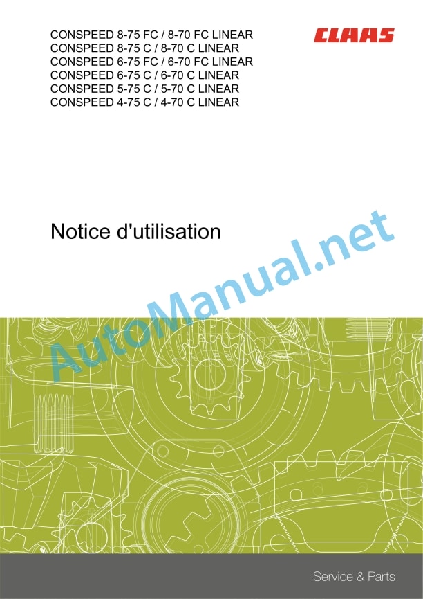
CONSPEED 8-75 FC / 8-70 FC LINEARCONSPEED 8-75 C / 8-70 C LINEARCONSPEED 6-75 FC / 6-70 FC LINEARCONSPEED 6-75 C / 6-70 C LINEARCONSPEED 5-75 C / 5-70 C LINEARCONSPEED 4-75 C / 4-70 C LINEAR
Contents
1 About this user manual
1.1 General information
1.1.1 Validity of the notice
1.1.2 Information regarding this user manual
1.1.3 Symbols and instructions
1.1.4 Optional equipment
1.1.5 Qualified specialist workshop
1.1.6 Notes on maintenance
1.1.7 Notes regarding warranty
1.1.8 Spare parts and technical questions
1.2 Use in accordance with instructions
1.2.1 Use in accordance with instructions
1.2.2 Reasonably foreseeable misuse
2 Security
2.1 Recognize the warnings
2.1.1 Warning pictogram
2.1.2 Signal word
2.2 Safety tips
2.2.1 Meaning of the instructions for use
2.2.2 Observe warning pictograms and warnings
2.2.3 Requirements for all people who work with the machine
2.2.4 Risk areas
2.2.5 Do not stand between the machine and the front tool
2.2.6 Coupling the machine to the front implement or transport trolley
2.2.7 Risk of injury due to rotating shafts
2.2.8 Construction modifications
2.2.9 Optional equipment and spare parts
2.2.10 Operation only after proper commissioning
2.2.11 Technical condition
2.2.12 Danger due to damage to the machine
2.2.13 Maintain protective devices capable of operating
2.2.14 Personal safety equipment
2.2.15 Wear suitable clothing
2.2.16 Remove dirt and loose objects
2.2.17 Prepare the machine for road travel
2.2.18 Unsuitable operating consumables
2.2.19 Safety of use of operating consumables and secondary operating consumables
2.2.20 Environmental protection and disposal
2.2.21 Electrical discharge at the electrical system level
2.2.22 Liquids under pressure
2.2.23 Only carry out work on the machine when it is stopped
2.2.24 Maintenance and repair work
2.2.25 Machine parts and loads noted
2.2.26 Risks due to welding work
2.3 Safety marking on the machine
2.3.1 Structure of warning pictograms
2.3.2 Position of warning pictograms
3 Description of the machine
3.1 Overview and mode of operation
3.1.1 Overview of CONSPEED LINEAR
3.1.2 CONSPEED LINEAR operating mode
3.2 Nameplates and identification numbers
3.2.1 Corn header nameplate
3.3 Optional machine equipment
3.3.1 Pinion, feed auger speed
3.3.2 Main gearbox gear pairs
3.3.3 Counterblade of the chopping unit
3.3.4 Skid heightening
3.3.5 Hood raise
3.3.6 Sunflower kit
3.3.7 Auger for poured corn
3.3.8 Stubble breakers
3.3.9 Skates
3.3.10 Cob recovery rubber
3.3.11 Safety bar
3.3.12 AUTO CONTOUR
3.3.13 AUTOPILOT
3.3.14 Transport trailer*
4 Technical characteristics
4.1 CONSPEED LINEAR
4.1.1 Dimensions
4.1.2 Weight
4.1.3 Bodywork
4.1.4 Lubricants
5 Preparing the machine
5.1 Disconnect and secure the machine
5.1.1 Disconnect the machine and secure it
5.2 Before commissioning
5.2.1 To be carried out before the first commissioning
5.2.2 To be carried out before each commissioning
5.2.3 Install the switch
5.3 Assembling the front tool
5.3.1 Install the hood tip
5.3.2 Adjust the transport position of the hood tip
5.3.3 Install thatch breakers*
5.3.4 Install the skids*
5.3.5 Install the power socket* for protection bar
5.3.6 Install the counter-blade of the chopping unit*
5.3.7 Install the cob recovery rubber*
Corn recovery rubber* to screw on
Corn recovery rubber* to insert
5.4 Load the front tool
5.4.1 Load the front implement and secure it
5.5 Install the front tool
5.5.1 Install the front tool
5.5.2 Adapt the machine
5.5.3 Select the cardan shaft
5.5.4 Modify the position of the cardan shafts
Check the cardan shaft
Remove the cardan shaft
Install the cardan shaft
5.5.5 Hanging the front tool
5.5.6 Lock the front tool
5.5.7 Install the multiple coupling
5.5.8 Install the cardan shaft
5.5.9 Bring the crutches backwards
5.5.10 Check the scraper profile
5.5.11 Learn the end stops of the hydraulic adjustment of picking plates
5.6 Remove the front tool
5.6.1 Remove the front tool
5.6.2 Remove the multiple coupling
5.6.3 Remove the cardan shaft
5.6.4 Unlock the front tool
5.6.5 Take out the crutches
5.6.6 Unhook the front tool
5.7 Prepare for road travel
5.7.1 Install the protection bar*
5.7.2 Install the protection bar
5.7.3 Install protective cloths
5.8 Prepare the work
5.8.1 Remove the protective cloths
5.8.2 Remove the safety bar
6.1 Traveling on the road
6.1.1 Traveling on the road
6.1.2 Fold the front tool into transport position
6.2 Work
6.2.1 Work
6.2.2 Unfold the front tool into the working position
6.3 Power group
6.3.1 Adjust the feed speed
6.3.2 Modify the feed auger speed
6.4 Picking device
6.4.1 Adjusting the fairing tip
Approximate adjustment
Precise adjustment of the central fairing points
Precise adjustment of the outer fairing tips
6.4.2 Lock the cover
6.4.3 Place the fairing in the maintenance position
6.4.4 Mechanically adjust the picking plates
6.4.5 Hydraulically adjust the picking plates
7 Incidents and remedies
7.1 Front tool
7.1.1 Overview of failures on CONSPEED
8 Maintenance
8.1 Overview of maintenance frequencies
8.1.1 Before the start of the harvest
8.1.2 After the first 10 hours of operation
8.1.3 After the first 20 hours of operation
8.1.4 After the first 50 hours of operation
8.1.5 Every 10 operating hours
8.1.6 Every 50 operating hours
8.1.7 Every 100 operating hours
8.1.8 Every 150 hours of service
8.1.9 Every 250 operating hours
8.1.10 Every 500 operating hours or every year
8.1.11 After harvest
8.2 Transmission, clutch and cardan shaft
8.2.1 Replace the main gearbox oil
Drain the oil
Pour the oil
8.2.2 Check the main gearbox oil level
8.2.3 Replace the header gearbox oil
Drain the oil
Pour the oil
8.2.4 Check header gearbox oil
8.2.5 Check feed auger drive overload coupling
8.3 Workouts
8.3.1 Check the chain tension
8.4 Picking device
8.4.1 Adjust the scraper plates
8.4.2 Adjust the picking plate support to the basic setting
8.4.3 Check the harvester drum knives
8.4.4 Replace the picker roller knives
8.4.5 Adjusting the feed chains
8.4.6 Clean the feed chain
8.5 Hashing
8.5.1 Replacing the chopper knives
8.5.2 Check the chopper knives
8.5.3 Check the tightening torque of the chopper knives
8.6 Lubrication plan
8.6.1 Lubricate the lubrication points every 10 operating hours
8.6.2 Lubricate the lubrication points every 50 operating hours
8.6.3 Lubricate the lubrication points every 100 operating hours
Rear lubrication points every 100 hours of service
Lubrication points before every 100 operating hours
8.6.4 Lubricate the lubrication points every 250 operating hours
9 Decommissioning and disposal
9.1 General information
9.1.1 Decommissioning and disposal
10 CE declaration of conformity
10.1 CONSPEED LINEAR
10.1.1 Declaration of conformity for EEC
John Deere Repair Technical Manual PDF
John Deere Transmission Control Unit Component Technical Manual CTM157 15JUL05
John Deere Repair Technical Manual PDF
John Deere Parts Catalog PDF
John Deere Tractors 6300, 6500, and 6600 Parts Catalog CQ26564 (29SET05) Portuguese
John Deere Repair Technical Manual PDF
John Deere Repair Technical Manual PDF
New Holland Service Manual PDF
John Deere Repair Technical Manual PDF
John Deere Diesel Engines POWERTECH 2.9 L Component Technical Manual CTM126 Spanish
John Deere Repair Technical Manual PDF


