Claas Disco 3100 Fc Frc (639) Mower Operator Manual ES
$50.00
- Model: Disco 3100 Fc Frc (639) Mower
- Type Of Manual: Operator Manual
- Language: ES
- Format: PDF(s)
- Size: 14.9 MB
File List:
00 0295 838 5.pdf
00 0295 838 5.pdf:
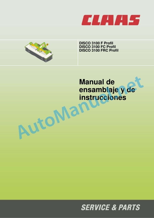
DISC 3100 F Profile
DISC 3100 FC Profile
DISC 3100 FRC Profile
1 Regarding this instruction manual
1.1 Information regarding the instruction manual
1.1.1 General instructions
1.1.2 Manual handling
Direction signs
1.1.3 Validity of the manual
1.1.4 Symbols and indications
1.1.5 Technical instructions
2 Security
2.1 Safety instructions
2.1.1 To take special account
2.1.2 Qualification of piloting and maintenance personnel
2.1.3 Proper machine application
2.1.4 Logically foreseeable inappropriate application
2.1.5 Protection and safety standards at work
2.1.6 First aid measures
2.1.7 Risk of injury from hydraulic fluid
2.2 Safety instructions on the machine
2.2.1 Warning symbols
2.2.2 Position of warning symbols
3 Machine Description
3.1 Summary and operation
3.1.1 Summary DISCO 3100 F Profile
3.1.2 Summary DISCO 3100 FC Profil / FRC Profil
3.1.3 DISCO 3100 F Profil operating mode
3.1.4 DISCO 3100 FC Profil operating mode
3.1.5 DISCO 3100 FRC Profil operating mode
3.2 Optional machine equipment
3.2.1 High cut skates
3.2.2 Low cut skates
3.2.3 Screw-on wear pads
3.2.4 Insertable fork for cardan shaft 8 components
3.2.5 Three-point elevation
3.2.6 Hydraulically foldable protective stirrups
3.2.7 ACTIVE FLOAT front hydraulic discharge
3.2.8 Hydraulic kit – AXION 800 with 5 ton lifting mechanism
3.2.9 Legal equipment France
3.3 Identification plate and vehicle identification number
3.3.1 Spare parts and technical queries
3.3.2 Nameplate position
3.3.3 Identification number position
3.3.4 Machine identification plate explanation
4 Control and display instruments
4.1 Mower unit
4.1.1 Latch
4.1.2 Latch
4.2 Conditioner
4.2.1 Lever
4.2.2 Cross handle
5 Technical data
5.1 DISC 3100 F Profile – Type 623
5.1.1 Measurements
5.1.2 Weights
5.1.3 Requirements for the tractor
5.1.4 Model
5.1.5 Acoustic intensity level
5.1.6 Inputs and filling quantities
5.2 DISC 3100 FC Profile – Type 639
5.2.1 Measurements
5.2.2 Weights
5.2.3 Requirements for the tractor
5.2.4 Model
5.2.5 Acoustic intensity level
5.2.6 Inputs and filling quantities
5.3 DISC 3100 FRC Profile – Type 639
5.3.1 Measurements
5.3.2 Weights
5.3.3 Requirements for the tractor
5.3.4 Model
5.3.5 Acoustic intensity level
5.3.6 Inputs and filling quantities
6 Assemble the machine
6.1 DISC 3100 F Profile – Type 623
6.1.1 Unpack
6.1.2 Assembling the left/right crash bar
6.1.3 Installing the front/rear crash bar
6.1.4 Assemble the left/right protection shields
6.1.5 Mount the protective guards front/rear
6.2 DISC 3100 FC Profile – Type 639
6.2.1 Unpack
6.2.2 Assembling the left/right crash bar
6.2.3 Install the front crash bar
6.2.4 Assemble the left/right protection shields
6.2.5 Assemble the front protection shield
6.2.6 Assemble the left/right swath plates
6.2.7 Assemble the guide plates
6.2.8 Assemble the rear protection shield
6.3 DISC 3100 FRC Profile – Type 639
6.3.1 Unpack
6.3.2 Assembling the left/right crash bar
6.3.3 Install the front crash bar
6.3.4 Assemble the left/right protection shields
6.3.5 Assemble the front protection shield
6.3.6 Assemble the left/right swath plates
6.3.7 Assemble the rear protection shield
6.4 Mower blades
6.4.1 Assembling the mower blades
7 Preparation of the machine
7.1 Adapt the tractor
7.1.1 Axle loads, minimum counterbalance, total weight
7.1.2 Calculate the minimum front counterbalance
7.1.3 Calculate the minimum rear counterweight
7.1.4 Calculate the actual front axle load
7.1.5 Calculate the actual total weight
7.1.6 Calculate the real rear axle load.
7.1.7 Calculation table
7.1.8 Adjust the front linkage
7.1.9 Assemble the three-point lift*
7.1.10 Assemble the support for the discharge springs
7.1.11 Assemble the connecting pieces for the discharge springs
7.1.12 Recommendation for mounting the support for discharge springs
CLAAS AXION 840
CLAAS ARES 836 RZ
CLAAS ARES 836 RZ
CLAAS ARES 696 RZ
CLAAS ARES 696 RZ
CLAAS CELTIS 446 RX
Fendt Vario Favorit 716
7.1.13 Mounting kits for support for discharge springs
CLAAS AXION 800
CLAAS ARES
CLAAS ARION 600 / 600 C / 500
CLAAS ARION 400
CLAAS AXOS
CLAAS ELIOS
CLAAS CELTIS
Fendt 900 Vario (new)
Fendt 800 Vario (new)
Fendt 800 Vario (old) / 700 Vario / 400 Vario
Fendt 309 Vario / 309 Ci / 307 Vario
Fendt 300 Vario
7.1.14 Assemble the support for the front hydraulic discharge
7.1.15 Assemble the connecting pieces for the front hydraulic discharge
7.1.16 Mounting recommendations for the front hydraulic discharge bracket
CLAAS AXION 800
CLAAS ARION 600 / 600 C / 500
CLAAS ARION 600
CLAAS ARION 400
CLAAS AXOS 300
CLAAS ELIOS
Fendt 900 Vario (new)
Fendt 800 Vario (new)
Fendt 800 Vario (old) / 700 Vario / 400 Vario
Fendt 309 Vario / 309 Ci / 307 Vario
Fendt 300 Vario
Fendt 600 Vario (old)
7.2 Turn off the machine and secure it
7.2.1 Turn off the machine and secure it
7.2.2 Secure the lifted machine
7.3 Adapt the machine
7.3.1 Adapt to left-turn power take-off
7.3.2 Cardan shaft for CLAAS Celtis 446 RX
7.3.3 Cardan shaft – check the length
7.3.4 Cardan shaft – adapt the length
7.3.5 Mount the cardan shaft to the machine
7.3.6 Conditioner speed
7.3.7 Adjust hydraulic discharge*
7.4 Hooking up the machine
7.4.1 Prepare the assembly
7.4.2 Pick up the machine
7.4.3 Check/adjust closure
7.4.4 Attach the protective breastplate
7.4.5 Check the protection breastplate
7.4.6 Deploy the latch
7.4.7 Deploy the latch
7.4.8 Assemble the cardan shaft
7.4.9 Adjust the third point arm
7.4.10 Hook the discharge springs
7.4.11 Engage the front hydraulic discharge*
Check the hitch position
7.4.12 Attaching the hydraulically foldable crash bars*
7.5 Dismantle the machine
7.5.1 Fold the latch
7.5.2 Fold the latch
7.5.3 Unhook the protection breastplate
7.5.4 Unhook the discharge springs
7.5.5 Disengage the front hydraulic discharge*
7.5.6 Detaching the hydraulically foldable crash bars*
7.5.7 Dismantle the cardan shaft
7.5.8 Lower the machine
7.6 Prepare for road traffic
7.6.1 Turn the protection bracket upwards
7.6.2 Lifting in transport position
7.7 Prepare for use at work
7.7.1 Turn the protection bracket downwards
7.8 Machine loading
7.8.1 Load/unload the machine
7.8.2 Load/unload the machine
8 Management
8.1 General security measures
8.1.1 Take into account before handling
8.2 Driving on the road
8.2.1 Road traffic
8.2.2 Machine marking for road traffic
8.3 Settings for use at work
8.3.1 Adjust ground adaptation
8.3.2 Adjust cutting height
8.3.3 Adjust the tine conditioner
8.3.4 Adjust swath width
8.3.5 Adjusting the wide spreading device
8.3.6 Mow without conditioning effect
8.4 Use at work
8.4.1 Take into account during field trips
8.4.2 Use the machine
Optimal power take-off speed
8.4.3 Mowing technique
8.4.4 Instructions on mowing
8.4.5 Difficult harvest conditions
8.4.6 Recommendation regarding environmental protection
9 Incident and solution
9.1 causes and solution
9.1.1 General warning instructions
9.1.2 General fault and solution
10 Maintenance
10.1 Maintenance instructions
10.1.1 General warning instructions
10.1.2 Electrical equipment
10.1.3 Protection devices
10.1.4 Spare parts
10.1.5 Imbalance
10.1.6 Pressurized air and water
10.1.7 Prevention against burns
10.1.8 Oil
10.1.9 Prevention against fires and explosions
10.1.10 Pipes, tubes and hoses
10.2 Summary of maintenance intervals
10.2.1 Management of maintenance intervals
10.2.2 before starting the harvest
10.2.3 After the first 50 hours of service
10.2.4 Every 8 hours of service
10.2.5 Every 20 hours of service
10.2.6 Every 100 hours of service
10.2.7 Every 250 hours of service
10.2.8 Every 500 hours of service or annually
10.2.9 if necessary
10.2.10 After harvest
10.3 General maintenance work
10.3.1 Clean the machine
10.3.2 Maintain the machine
10.3.3 Fixing material
10.4 Gear maintenance work
10.4.1 Check the tightness of the gear
10.4.2 Main gear
10.4.3 Main gear
10.4.4 Bevel gear
10.5 Maintenance work on the clutch
10.5.1 Adjust the friction clutch
10.5.2 Ventilate the friction clutch
10.5.3 Replacing the friction discs
10.6 Cardan shaft maintenance work
10.6.1 Maintain the cardan shafts
10.7 Maintenance work on the mowing device
10.7.1 Check the oil level in the cutter bar
10.7.2 Change the cutter bar oil
10.7.3 Remove the mower blade box
10.7.4 Take into account the direction of rotation of the mowing discs
10.7.5 Check the mower blades
10.7.6 Change the blades
10.7.7 Check the mower blade support
10.7.8 Maintenance of mower discs
10.7.9 Change the mower discs
10.7.10 Assemble the bevel pinion units
10.7.11 Setting the winding protection
10.8 Maintenance work on the conditioner
10.8.1 Tension the drive belt
10.8.2 Change the drive belt
10.8.3 Assembling/disassembling conditioner tines
10.8.4 Adjust the roller conditioner
10.9 Maintenance work on the swath disc
10.9.1 Adjust the right swath disc
10.10 Maintenance work on protective devices
10.10.1 Adjust the protection device
Protective canvas support, front
Left/right protective breastplate support
10.11 Maintenance work on the chassis
10.11.1 Adjust the latch for assembly and disassembly
10.11.2 Adjust ground adaptation
10.11.3 Adjust ground adaptation
10.12 Greasing scheme
10.12.1 Greasing points – 8 h
10.12.2 Greasing points – 20 h
10.12.3 Greasing points – 100 h
10.12.4 Grease points – 250 h
11 Decommissioning and waste disposal
11.1 General data
11.1.1 End of operational life and waste disposal
12 EU declaration of conformity
12.1 DISC 3100 F Profil / FC Profil / FRC Profil
12.1.1 EC declaration of conformity
13 Technical dictionary and abbreviations
13.1 Terms and explanations
13.1.1 Technical vocabulary
13.1.2 Abbreviations
John Deere Repair Technical Manual PDF
John Deere Repair Technical Manual PDF
John Deere Repair Technical Manual PDF
John Deere Repair Technical Manual PDF
John Deere Repair Technical Manual PDF
John Deere 16, 18, 20 and 24HP Onan Engines Component Technical Manual CTM2 (19APR90)
John Deere Repair Technical Manual PDF
John Deere Parts Catalog PDF
John Deere Tractors 7500 Parts Catalog CPCQ26568 30 Jan 02 Portuguese
John Deere Repair Technical Manual PDF
John Deere Application List Component Technical Manual CTM106819 24AUG20
John Deere Repair Technical Manual PDF
John Deere DF Series 150 and 250 Transmissions (ANALOG) Component Technical Manual CTM147 05JUN98


