Claas Disco 8550 (652) Mower Operator Manual EN
$50.00
- Model: Disco 8550 (652) Mower
- Type Of Manual: Operator Manual
- Language: EN
- Format: PDF(s)
- Size: 111 MB
File List:
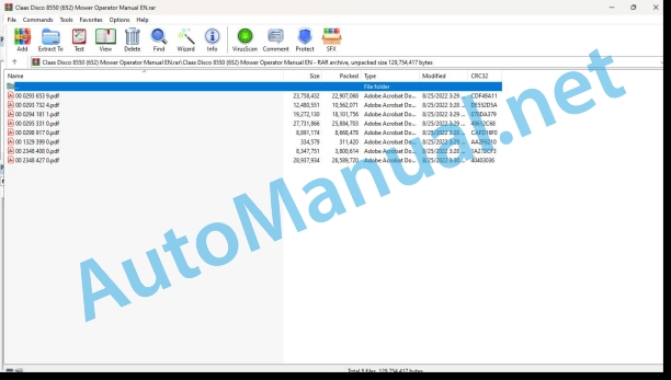
00 0293 653 9.pdf
00 0293 732 4.pdf
00 0294 181 1.pdf
00 0295 331 0.pdf
00 0298 917 0.pdf
00 1329 399 0.pdf
00 2348 408 0.pdf
00 2348 427 0.pdf
00 0293 653 9.pdf:
1 Introduction
Introduction
2 Table of contents
3 Preface
Of special importance
Identification plate
4 Safety Rules
Intended use
Identification of warning and dan ger signs
General safety and accident pre vention instructions
Attached machines
Attached devices
PTO Operation
Hydraulic system
Maintenance
Sound pressure level
Safety decals with pictorials
5 Specifications
Calculating the axial loads, minimum ballast and total weight
Calculation of the minimum front ballast
Calculation of the minimum rear ballast
Calculation of the actual front axle load
Calculation of the actual overall weight
Calculation of the actual rear axle load
Carrying capacity of the tyres
Noise level
6 Prior to Operation
Assembly
Side mower safety frame DISCO 8550 C Plus / 8550 C / 8550 C-T / 8500 C
Side mower safety frame DISCO 8550 Plus / 8550
Mounting the fitting frame
Fitting the controller – DISCO 8550 C Plus / 8550 C / 8550 C-T
Fitting the controller – DISCO 8550 C Plus / 8550 C / 8500 C-T
Use as a pushed combination
Fitting the adapter (B03 0030)
Fitting the Accord coupling
Fitting the lighting unit on the front mower unit
Use as a towed front – rear combination
Fitting the lighting unit
Fitting the middle mower unit rotation sensor DISCO 8550 C Plus / 8550 C / 8550 C-T
Setting the clearance height DISCO 8550 C Plus / 8550 C / 8550 C-T
Fitting the blades
Matching the universal drive shaft
Loading/unloading the machine DISCO 8550 Plus / 8550
Check and observe the following before putting into operation!
Attachment to the tractor
Hooking up the fitting frame
Hooking up the front mower unit to the fitting frame
Setting the upper link
Weight relief
Connecting the universal drive shaft
Hydraulic system
Electrical system
Removing the machine
Lowering the machine in the unfolded condition
Lowering the machine in the folded condition
Conversion from front – rear combina tion to pushed combination
Conversion from pushed combination to front – rear combination
Prior to transportation
Driving on public roads
7 Operation
Control system DISCO 8550 C Plus / 8550 C / 8550 C-T
Working position
Transport position
Mowing with individual units raised
Headland setting
Rotation monitoring
Bridging out switch
Control system DISCO 8550 Plus / 8550 / 8500 C
Working position
Transport position
Mowing without side mowing units
Operation
Setting the cutting height
Safety equipment
Conditioner
Chicane plates
Changing the conditioner speed
Changing the swathe width
Recommendations for environmental protection
Collision protection
Emergency functions
Optional equipment
High cutting runners
Push-on runners
8 Maintenance
Important maintenance instructions
Hydraulic system
Energy accumulators
Lubrication
Safety devices
Drive System
Tensioning the conditioner drive belt
Main gearbox DISCO 8550 C Plus / 8550 C / 8550 C-T / 8500 C
Main gearbox DISCO 8550 Plus / 8550
Side gearbox
Universal drive shaft
Mower head
Mower blades
Mower blade box
Changing mower blades DISCO 8550 C Plus / 8550 Plus / 8550 C-T
Changing mower blades DISCO 8550 Plus / 8550 / 8500 C
Mower discs
Replacing cutting discs
Suspension springs
Quick setting of the spring length
Final setting of the spring length
Conditioner tines
Fitting / removing the tines
Electrical system
Setting the rotation sensors
Setting the lift sensors
Replacing the wiring loom
Hydraulic system
Hydraulic hoses
Hydraulic cylinder with vacuum valve
Lubrication openings
Clutches
Maintenance of the friction and overrunning clutch
Screw connections
Connecting elements
End of season storage
Malfunctions
9 Lubrication chart
Safety Rules
Lubricants
Lubrication
00 0293 732 4.pdf:
DISCO 8550 AS Plus
Assembly and operating instructions
1 Introduction
Introduction
2 Contents
3 Preface
Of special importance
Identification plate
4 Safety rules
Identification of warning and hazard signs
Intended use
Avoidable incorrect applications
General safety and accident prevention regulations
Attached machines
Trailed machines
PTO operation
Hydraulic system
Maintenance
Noise pressure level
De-commissioning and disposal
Safety decals with pictorials
5 Specifications
DISCO 8550 AS Plus
Noise pressure level
Measuring system
6 Assembly
Unloading / loading the machine
Assembling the mower unit
Use as a front-rear combination
Safety frame side mower units
Fitting the mounting frame
Fitting the control system
Fitting the side mower units into the arms
Setting the clearance height
Fitting the blades
Checking the length of the universal drive shaft
Preparing the mower unit
Removing the safety cover/shifting the cover
Folding the safety guard
Shifting the guide plates on the width control
Attaching the outer guide plates
Adjusting outer guide plates
Fitting the swath displacer for the first time
Fitting the hose line
Mounting the central frame
Attaching the central frame to the mower unit
Hydraulic connection
Electrical connections
Attaching the belts to the supporting arms of the swath displacer
Check and adjust the setting of the belts to the mower unit
Mounting the counter balance springs
Mounting floatation springs to the supporting arms
Adjusting the braces
Coupling the swath displacer to the mower units
Setting the belt conveyor and mower unit in transport position
Connecting hose lines to the oil motors
Mounting the lighting
7 Prior to Operation
Adjustments to the tractor
Calculation of axle loads, minimum ballasting and total weight
Calculation of the minimum front ballasting
Calculation of the minimum rear ballasting
Calculation of the actual front axle load
Calculation of the actual total weight
Calculation of the actual rear axle load
Tyre payload
Fitting the mower unit
Hooking up the mounting frame
Connecting the universal drive shaft
Hydraulic system
Electrical system
Mounting the swath displacer
Check and observe the following before putting into operation!
Unhitching the swath displacer
Uncoupling the swath displacer from the mower unit
Removing the floatation springs from the supporting arms
Disconnecting electrical connections
Disconnecting the hydraulic system
Mounting the safety devices
Repositioning the guide plates of the width control
Adjusting guide plates
Mounting the mower unit with swath displacer
Lowering the machine in the unfolded condition
Lowering the machine in the folded condition
Prior to transportation
Driving on public roads
8 Operation
Control system
Working position
Transport position
Mowing with individual units raised
Headland setting
Rotation monitoring
Bridging out switch
Adjusting the belt speed
Operation
Function of the swath displacer
Mowing with swath displacers
Before mowing
Setting up the swath displacer
Adjusting the flap
Adjusting the guide plates of the width control
Adjusting outer guide plates
Adjusting the swath width
Oil cooler for the on-board hydraulics
Mowing without the swath displacer
Raising and lowering the left and right-hand belts
Safety devices
Fitting the safety devices
Folding the safety guard
Repositioning the guide plates of the width control
Adjusting guide plates
Setting the cutting height
Conditioner
Deflector plates
Changing the speed of the conditioner
Recommendations for environmental protection
Collision protection
Emergency functions mower unit
Emergency functions swath displacer
Additional equipment
High cutting runners
Push-on runners
Crop spreader
Hydraulic connections for tractors
Adapter for lighting in the USA
9 Maintenance
Important maintenance instructions
Hydraulic system
Energy accumulators
Bolts and screws
Lubrication
Safety devices
Drive System
Tensioning the conditioner drive belt
Main gearbox mower unit
Reduction gearbox, mower unit
Pump gearbox swath displacer
Filling with oil
Oil change
Clutches
Maintenance of the friction and overrunning clutch
Universal drive shaft
Mower head
Mower blades
Mower blade box
Change mower blades.
Mower blade quick-change system
Mower blade bracket (mower blade quick-change system)
Mowing discs
Replacing mowing discs
Conditioner tines
Fitting / removing the tines
Floatation springs, mower unit
Quick setting of the spring length
Final setting of the spring length
Swath displacer
Setting the cross conveyor
Remove the belt conveyor
Setting the stripper
Setting the drive shaft
Tensioning the belt conveyor
Assembling the cross conveyor
Balance spring tension
Floatation springs supporting arms
Hydraulic system
Hydraulic hose connections
Hydraulic cylinder with vacuum valve
Hydraulic oil tank for the on-board hydraulics
Cleaning the oil cooler
Filling with oil
Oil change
Changing the filter
Electrical system
Setting the speed sensors
Setting the lifting sensors of the mower unit
Replacing the wiring loom
Setting the lifting sensors of the swath displacer
Lubrication openings
Screw connections
Fasteners
Cleaning and care
Winter storage
Malfunctions
10 Lubrication chart
Safety rules
Lubricants
Lubrication
00 0294 181 1.pdf:
1 Introduction
Introduction
2 Contents
3 Preface
Of special importance
Identification plate
4 Safety Rules
Intended use
Identification of warning and dan ger signs
General safety and accident pre vention instructions
Attached machines
Attached devices
PTO Operation
Hydraulic system
Maintenance
Sound pressure level
Safety decals with pictorials
5 Specifications
Calculating the axial loads, minimum ballast and total weight
Noise level
6 Assembly
Loading/unloading machine
Fit guard frames for side disc mow ers
Mounting the fitting frame
Fit operating terminal
Use as a pushed combination
Fitting the adapter (B03 0030)
Fitting the Accord coupling
Fitting the lighting unit on the front mower unit
Use as a towed front – rear combination
Fitting the lights unit
Fit speed sensor for centre mower unit
Set clearance height
Fitting blades
Adjust universal drive shaft
Attaching machine for first time
7 Prior to Operation
Check and observe the following before putting into operation!
Attachment to the tractor
Hooking up the fitting frame
Hooking up the front mower unit to the fitting frame
Setting the upper link
Weight relief
Connecting the universal drive shaft
Hydraulic system
Electrical system
Removing the machine
Lowering the machine in the unfolded condi tion
Lowering the machine in the folded condition
Conversion from front – rear combi nation to pushed combination
Conversion from pushed combination to front-rear combination
Prior to transportation
Driving on public roads
8 Operation
Controls
Working position
Transport position
Mowing with individual units raised
Headland setting
Rotation monitoring
Fault display:
Fault display:
Speed monitor override switch
Operation
Setting the cutting height
Safety equipment
Recommendations for environmental protection
Collision protection
Emergency functions
Optional equipment
High cutting runners
Push-on runners
9 Maintenance
Important maintenance instructions
Hydraulic system
Energy accumulators
Lubrication
Safety devices
Gearboxes
Main gearbox
Side gearbox
Mower head
Universal drive shaft
Clutches
Maintenance of the friction and overrunning clutch
Mower blades
Mower blade box
Change mower blades.
Mower blade quick-change system
Mower blade holder (Mower-blade quick-change sys tem)
Bolted mower blades
Fastening mower blades (bolted mower blades)
Mower discs
Replacing cutting discs
Mower disc cap
Fitting pinion units
Suspension springs
Quick setting of the spring length
Final setting of the spring length
Electrical system
Setting the lift sensors
Replace wiring loom for ejection sensors
Setting the rotation sensors
Hydraulic system
Hydraulic hoses
Hydraulic cylinder with vacuum valve
Safety devices
Fold-away guard frames
Sleeve protector
Lubrication openings
Screw connections
Connecting elements
End of season storage
Malfunctions
10 Lubrication chart
Safety Rules
Lubricants
Lubrication
00 0295 331 0.pdf:
1 Introduction
Introduction
2 Table of contents
3 Preface
Of special importance
Identification plate
4 Safety Rules
Intended use
Identification of warning and danger signs
General safety and accident prevention instructions
Attached machines
Attached devices
PTO Operation
Hydraulic system
Maintenance
Sound pressure level
Safety decals with pictorials
5 Specifications
Calculating the axial loads, minimum ballast and total weight
Calculation of the minimum front ballast
Calculation of the minimum rear ballast
Calculation of the actual front axle load
Calculation of the actual overall weight
Calculation of the actual rear axle load
Carrying capacity of the tyres
Noise level
Measuring procedure
6 Prior to Operation
Assembly
Side mower safety frame DISCO 8550 C Plus / 8550 C / 8550 C-T / 8500 C
Side mower safety frame DISCO 8550 Plus / 8550
Mounting the fitting frame
Fitting the controller – DISCO 8550 C Plus / 8550 C / 8550 C-T
Fitting the controller – DISCO 8550 C Plus / 8550 C / 8500 C-T
Use as a pushed combination
Fitting the adapter (B03 0030)
Fitting the DISCO 3100 FC (B03 0060) adapter
Fitting the Accord coupling
Fitting the lighting unit on the front mower unit
Use as a towed front – rear combination
Fitting the lighting unit
Fitting the speed sensor of the front mower unit DISCO 3100 FC
Fitting the speed sensor of the front mower unit (except DISCO 3100 FC)
Setting the clearance height DISCO 8550 C Plus / 8550 C / 8550 C-T
Fitting the blades
Checking the length of the universal drive shaft
Loading/unloading the machine DISCO 8550 Plus / 8550
Check and observe the following before putting into operation!
Attachment to the tractor
Hooking up the fitting frame
Fitting the mounting frame with adapter (B03 0050)
XERION or tractors with large tyres
Hooking up the front mower unit to the fitting frame
Setting the upper link
Weight relief
Connecting the universal drive shaft
Hydraulic system
Electrical system
Removing the machine
Lowering the machine in the unfolded condition
Lowering the machine in the folded condition
Conversion from front – rear combination to pushed combination
Conversion from pushed combination to front – rear combination
Prior to transportation
Driving on public roads
7 Operation
Control system DISCO 8550 C Plus / 8550 C / 8550 C-T
Working position
Transport position
Mowing with individual units raised
Headland setting
Rotation monitoring
Bridging out switch
Control system DISCO 8550 Plus / 8550 / 8500 C
Working position
Transport position
Mowing without side mowing units
Operation
Setting the cutting height
Safety equipment
Conditioner
Chicane plates
Changing the speed of the conditioner
Changing the swathe width
Recommendations for environmental protection
Collision protection
Emergency functions
Optional equipment
High cutting runners
Push-on runners
Xerion adapter
Xerion connection kit
Crop spreader
Hydraulic connections for tractors
Adapter for lighting in the USA
8 Maintenance
Important maintenance instructions
Hydraulic system
Energy accumulators
Lubrication
Safety devices
Drive System
Tensioning the conditioner drive belt
Main gearbox DISCO 8550 C Plus / 8550 C / 8550 C-T / 8500 C
Main gearbox DISCO 8550 Plus / 8550
Side gearbox
Universal drive shaft
Mower head
Mower blades
Mower blade box
Changing mower blades DISCO 8550 C Plus / 8550 Plus / 8550 C-T
Changing mower blades DISCO 8550 Plus / 8550 / 8500 C
Mower discs
Replacing cutting discs
Suspension springs
Quick setting of the spring length
Final setting of the spring length
Conditioner tines
Fitting / removing the tines
Electrical system
Setting the rotation sensors
Setting the lift sensors
Replacing the wiring loom
Hydraulic system
Hydraulic hoses
Hydraulic cylinder with vacuum valve
Lubrication openings
Clutches
Maintenance of the friction and overrunning clutch
Screw connections
Connecting elements
Care and cleaning
End of season storage
Malfunctions
9 Lubrication chart
Safety Rules
Lubricants
Lubrication
00 0298 917 0.pdf:
Supplement to the operating instructions and spare parts list
DISCO 8550 C Plus
1 Introduction
Introduction
2 Contents
3 Preface
Of particular note
4 For safety
Labeling of warnings and danger notices
Safety sticker with warning symbols
5 Technical data
DISCO 8550 AS Plus
6 Before commissioning
Use as a front-rear combination
Attachment of swath movers
Hydraulic installation
Check and observe before commissioning!
7 Operation
Function of the swath movers
Before mowing
Adjusting the swath offsetrs
Throwing distance
Direction of throw
Throw height
Swath formation
8 Maintenance
Important maintenance instructions
Hydraulic system
lubrication
Protective devices (protective bars)
Tension of the conveyor belt
Hydraulics
Hydraulic hose lines
9 Spare parts list
Side unit for cross conveyor belt
Boom/spring relief
Cross conveyor belt
Hydraulics
Supplement to operator’s manual and spare parts list
DISCO 8550 C Plus
1 Introduction
Introduction
2 contents
3 Preface
Of special importance
4 safety instructions
Identification of warnings and danger signs
Safety decals with warning symbols
5 specifications
DISCO 8550 AS Plus
6 Before Surgery
Use as a front/rear combination unit
Mounting the swath grouper
Hydraulics installation
Check and observe the following before putting into operation!
7 operation
Function of swath grouper
Before mowing
Setting the swath groupers
Ejection range
Ejection direction
Ejection height
Swath formation
8Maintenance
Important Maintenance Instructions
Hydraulic system
Lubrication
Protective devices (safety frame)
DRIVE SYSTEMS
Conveyor belt tension
Hydraulic system
Hydraulic hose connections
9 Spare parts list
Lateral unit for cross conveyor
Arm / compensating spring
Cross conveyor
Hydraulic system
Supplement to the driftsvejledning and resevedelsliste
DISCO 8550 C Plus
1 Indledning
Indledning
2 Indhold
4 Sikkerhed
Mærkning af advarsler
Sikkerhedsmærkat with advarsels symbol
5 technical data
DISCO 8550 AS Plus
6 For ibrugtagning
Anvendelse som front-hæk combination
Montering on skårflytteren
Hydraulic installation
Bør controllers for ibrugtagning!
7 Betjening
Anvendelse
Skårflytterens function
For mejningen
Indstilling on skårflytterne
Castevidde
Kasteretning
Kastehøjde
Skårdannelse
8 Vedligeholdelse
Vigtige vedligeholdelsesanvisninger
Hydraulic system
Beskyttelsesanordninger (beskyttelsesbøjle)
Transportremmens spænding
Hydraulics
Hydraulic slangeledninger
9 reserve list
Sideenhed to the televisiobelt
udlæaflastning
tværtransportbånd
Hydraulics
00 2348 408 0.pdf:
CEMIS 100
Table of contents
1 Introduction
1.1 General information
1.1.1 Validity of the manual
1.1.2 Information about this Operator’s Manual
1.1.3 Symbols and notes
1.2 Intended use
1.2.1 Intended use
1.2.2 Reasonably foreseeable misuse
2 Safety
2.1 Safety rules
2.1.1 General safety and accident prevention regulations
2.1.2 Interaction between terminal and machine or tractor
2.1.3 Electrocution by electrical system
3 Product description
3.1 Overview and method of operation
3.1.1 Overview of CEMIS 100
3.1.2 Function principle of CEMIS 100
3.2 Identification plates and identification numbers
3.2.1 Spare parts and technical questions
3.2.2 Identification plate of CEMIS 100
4 Operating and display elements
4.1 CEMIS 100
4.1.1 User interface for LINER
4.1.2 User interface for ROLLANT
4.1.3 User interface for UNIWRAP
5 Teical specifications
5.1 CES 100
5.1.1 Specification
6 Operation
6.1 CEMIS 100
6.1.1 Operating the CEMIS 100
6.1.2 Switching CEMIS 100 on
6.1.3 Switching CEMIS 100 off
7 Maintenance
7.1 CEMIS 100
7.1.1 Daily
8 Putting out of operation and disposal
8.1 General information
8.1.1 Removal from service and disposal
9 Technical terms and abbreviations
9.1 Terms and explanations
9.1.1 Technical words
9.1.2 Abbreviations
00 2348 427 0.pdf:
CEMIS 700
Table of contents
1 Introduction
1.1 General information
1.1.1 Validity of the manual
1.1.2 Information about this Operator’s Manual
1.1.3 Symbols and notes
1.2 Intended use
1.2.1 Intended use
1.2.2 Reasonably foreseeable misuse
2 Safety
2.1 Safety rules
2.1.1 General safety and accident prevention regulations
2.1.2 Interaction between terminal and machine or tractor
2.1.3 Electrocution by electrical system
3 Product description
3.1 Overview and method of operation
3.1.1 Overview of CEMIS 700
3.1.2 Function principle of CEMIS 700
3.2 Identification plates and identification numbers
3.2.1 Spare parts and technical questions
3.2.2 Identification plate of CEMIS 700
4 Information on the product
4.1 Software version
5 Operating and display elements
5.1 CEMIS 700
5.1.1 User interface
5.1.2 Terminal program
6 Technical specifications
6.1 CEMIS 700
6.1.1 Specification
7 Operation
7.1 CEMIS 700
7.1.1 Operating the CEMIS 700
7.1.2 Switching CEMIS 700 on
7.1.3 Switching CEMIS 700 off
7.2 Terminal settings
7.2.1 Making settings
Making settings with the rotary button
Making settings with the touch function
7.2.2 Setting the screen lighting
Daytime mode
Nighttime mode
Activating automatic key lighting
7.2.3 Setting the time and date
7.2.4 Displaying diagnosis information
On-board power supply voltage display
Display of CLAAS ISOBUS ECU address and name
7.2.5 Setting the language and display formats
Setting the language
Setting display formats
7.2.6 Setting the volume
7.2.7 Deleting an ISOBUS implement
8 Maintenance
8.1 Maintenance
8.1.1 Daily
9 Putting out of operation and disposal
9.1 General information
9.1.1 Removal from service and disposal
10 Technical terms and abbreviations
10.1 Terms and explanations
10.1.1 Technical words
10.1.2 Abbreviations
John Deere Repair Technical Manual PDF
John Deere Repair Technical Manual PDF
John Deere Repair Technical Manual PDF
John Deere Repair Technical Manual PDF
John Deere Repair Technical Manual PDF
John Deere Parts Catalog PDF
John Deere Tractors 6300, 6500, and 6600 Parts Catalog CQ26564 (29SET05) Portuguese
John Deere Repair Technical Manual PDF
John Deere Repair Technical Manual PDF
John Deere PowerTech M 10.5 L and 12.5 L Diesel Engines COMPONENT TECHNICAL MANUAL CTM100 10MAY11
John Deere Repair Technical Manual PDF
John Deere Diesel Engines PowerTech 4.5L and 6.8L – Motor Base Technical Manual 07MAY08 Portuguese

