Claas Dominator 130 (456) Combines Technical System FR
$300.00
- Model: Dominator 130 (456) Combines
- Type Of Manual: Technical System
- Language: FR
- Format: PDF(s)
- Size: 31.1 MB
File List:
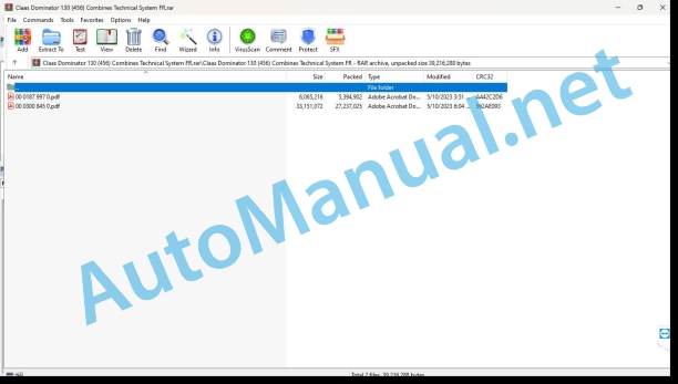
00 0187 997 0.pdf
00 0300 845 0.pdf
00 0187 997 0.pdf:
187997’0-HE-D0218-202MegaII-F-A3.pdf
00 0300 845 0.pdf:
DOMINATOR 130 type 456
Contents
CCN explanation
CCN (CLAAS Component Number)
Electrical standard
Overview
Hydraulic standard
Overview
CCN (CLAAS Component Number)
Introduction
Safety tips
Safety instructions and risk information
Validity of the notice
Validity of the notice
Directory of abbreviations
05 Management
0505 Steering
General steering system
Neutral functional diagram
Functional diagram steering activated
Management check
09 Hydraulic system
0905 Tank
Hydraulic oil tank
Hydraulic oil tank with filter
0910 Pumps
Hydraulic pumps
Tandem pump
0920 Valves
6-way 9-position multifunction valve (6037)
Valve cut
Designations
Description of the function
Hydraulic Valve Swivel Hopper Drain Tube (6019)
Valve cut
Designations
Description of the function
Working hydraulic system pressure limiter (7003).
Valve cut. Pressure limiter on machines with bagging platform
Designations
Description of the function
Stop Block (7034)
Valve cut
Designations
Description of the function
Flow divider (7069)
Valve cut. Flow divider (7069). Optional with horizontal reel adjustment.
Designations
Description of the function
Functional disturbances
Option. Hydraulic reel horizontal adjustment valve (6039)
Valve cut
Designations
Description of the function
Valve Block Reverse Front Tool (Y086)
Valve cut
Designations
Description of the function
Hydraulic pendulum control valve for 3-D cleaning shoe (6001)
Valve cut
Designations
Description of the function
Advance variator foot valve (6038)
Valve cut
Designations
Description of the function
Check valve with one-sided throttle (7060)
Valve cut
Designations
Description of the function
0925 Hydraulic motors
Hydraulic motor reverse front tool (2026)
Rotor mounting position
Description of the function
0930 Cylinders
Hydraulic cylinder variants – Air bleeding at end positions
Description of the function
Front implement reversing hydraulic cylinder (3053)
Hydraulic cylinder adjustment reverse front implement
Description of the function
Hydraulic Cylinder Swivel Hopper Drain Tube (3020)
Hydraulic cylinder for vertical adjustment of the reel (3014 + 3015)
Description of the function
Hydraulic cylinder horizontal adjustment of the reel
Description of the function
Hydraulic variator cylinder
Description of the function
0980 Hydraulic connection plan
Vehicle hydraulic system connection diagram
Connection diagram of the complete hydraulic system
Control and measure
10 Electrical/electronic system
1010 Central electrical system
Central electrical system
Central Electrical System Parts
1012 Modules – Sensors
Modules A092, A093, A094 – Speed controller (optional)
1080 Electronic connections plan
Introduction connection diagrams
Overview of designations
Cable designation
Cable color abbreviations according to ISO (IEC 60757)
Machine electrical connection diagrams (SCM) type 456
SCM 01- Main voltage supply, diesel engine starter
Designations
Measurement value table
Description of the function
Connector allocation:
Connections list
SCM 02 – Electrical voltage supply – start the diesel engine
Designations
Measurement value table
Description of the function
Connector allocation:
Connections list
SCM 03- Diesel engionitoring
Designations
Measurement value table
Description of the function
Connector allocation:
Connections list
SC – Flow control
Designations
Description of the function
Connector allocation:
Connections list
SCM 05- Reverse warning buzzer
Designations
Description of the function
Connector allocation:
Connections list
SCM 06- Reverse front tool
Designations
Measurement value table
Description of the function
Connector allocation:
Connections list
SCM 07- RPM monitoring (optional)
Designations
Measurement value table
Description of the function
Diet chart
Connector allocation:
Connections list
SCM 08- Operating displays
Designations
Measurement value table
Description of the function
Connector allocation:
Connections list
SCM 09- Rotating beacon (connection possible)
Designations
Description of the function
Connector allocation:
Connections list
SCM 10- Flashing, hazard lights
Designations
Description of the function
Connector allocation:
Connections list
SCM 11- Main lighting circuit, position lights, instrument lighting
Designations
Description of the function
Connector allocation:
Connections list
SCM 12 – Work lighting
Designations
Measurement value table
Description of the function
Connector allocation:
Connections list
SCM 13- Brake light
Designations
Description of the function
Connector allocation:
Connections list
SCM 14- Windshield wiper
Designations
Measurement value table
Description of the function
Connector allocation:
Connections list
SCM 15- Compressor air conditioning
Designations
Measurement value table
Description of the function
Connector allocation:
Connections list
SCM 16- Additional power sockets (connection possibilities)
Designations
Description of the function
Connector allocation:
Connections list
Location of parts
Hydraulic system
1000 Oil tank / filter
2000 Pump / Motor
3000 Main hydraulic cylinder
4000 Restrictor / Calibrated Orifice
6000 Valves – mechanical control
7000 Valves – hydraulic control
8000 Couplings / fittings
9000 Measuring points / display instruments
Electrical system
B Sensors
H Signaling device / indicator lights
R Potentiometer / resistor
S Switch / Button – cabin control
U Switch – external control
Y Electromagnetic coil
Z Actual value switch
John Deere Repair Technical Manual PDF
John Deere Parts Catalog PDF
John Deere Harvesters 8500 and 8700 Parts Catalog CPCQ24910 Spanish
John Deere Repair Technical Manual PDF
John Deere Repair Technical Manual PDF
John Deere Diesel Engines PowerTech 4.5L and 6.8L – Motor Base Technical Manual 07MAY08 Portuguese
New Holland Service Manual PDF
John Deere Repair Technical Manual PDF
John Deere Diesel Engines POWERTECH 2.9 L Component Technical Manual CTM126 Spanish
John Deere Repair Technical Manual PDF
John Deere Parts Catalog PDF
John Deere Tractors 7500 Parts Catalog CPCQ26568 30 Jan 02 Portuguese
John Deere Repair Technical Manual PDF


